WB-MRWL3 Modbus Relay Modules/en: различия между версиями
(Новая страница: «{| class="wikitable" |- |Maximum switching current, resistive load 230V AC |20A |- |Maximum allowable inrush current (within 20ms, for no contact) |30A |- |Conta…») |
FuzzyBot (обсуждение | вклад) (Часть переводимой страницы WB-MRWL3 Modbus Relay Module.) |
||
| (не показано 25 промежуточных версий 2 участников) | |||
| Строка 60: | Строка 60: | ||
|} | |} | ||
=== | === Inputs === | ||
[[ | [[File:Input_modes.png|420px|thumb|left|Closed input in trigger mode may be unstable]] | ||
The inputs of the WB-MRWL3 modules are led out on detachable screw terminals. Inputs are organized on the dry contact principle. Buttons or switches are connected between the corresponding inputs and iGND inputs. | |||
3 | The 3 inputs can be used for direct control of the respective relay channels. Another input can be used for group disconnection of all channels. | ||
The inputs have two modes of operation: trigger mode (for control with buttons) and repeat mode (for control with switches). In the trigger mode, to change the state of the relay, it is enough to close and open the input once. The change of state occurs on the rising edge (that is, when the circuit). In the repeat mode, the relay state is determined by the input state: the input is closed — the relay is on, open — off. Details about the mode switching written in [[ Modbus Management Of Relay Modules/en|Modbus Management Of Relay Modules]]. | |||
''' | '''IMPORTANT:''' it is not recommended to use switches (lock buttons) in the trigger mode of inputs. Input interference may be perceived as a short release/push of the button and the relay status will change, although the switch will remain closed. | ||
== | ==Technical specifications== | ||
{| border="1" class="wikitable" style="text-align:left" | {| border="1" class="wikitable" style="text-align:left" | ||
|- | |- | ||
! | !Parameter | ||
! | !Value | ||
|- | |- | ||
! colspan="2" | | ! colspan="2" |Power | ||
|- | |- | ||
| | |Supply voltage | ||
|12 — 28 | |12 — 28 V DC | ||
|- | |- | ||
| | |Power consumption | ||
| | | | ||
* | *Idle mode (All relays switched off) — 0.5 W | ||
* | *All relays switched on — 2 W | ||
* | *Peak value — up to 5 W for 20 MS | ||
|- | |- | ||
!colspan="2" | ''' | !colspan="2" | '''Terminals and wire section''' | ||
|- | |- | ||
|| | || Recommended wire cross-section with NSUI, mm<sup>2</sup>|| 0,75 — 1 for control inputs, 2 x 2.5 for relay outputs | ||
|- | |- | ||
|| | || Length of the standard sleeve NSVE, mm || 8 (10 for relay outputs) | ||
|- | |- | ||
|| | || Torque of screws, N∙m || 0,2 for control inputs , 0,4 — for power outputs | ||
|- | |- | ||
! colspan="2" |''' | ! colspan="2" |'''Outputs''' | ||
|- | |- | ||
| | |Output type | ||
| | |Mechanical relay contacts | ||
|-|- | |-|- | ||
| | |Output configuration | ||
|3 | |3 / output connected to the relay contacts | ||
|- | |- | ||
| | |Configuration of each output contacts | ||
| | |Two-position, normally open (S and NO) | ||
|- | |- | ||
| | |Maximum switching voltage, AC | ||
|250 | |250 V | ||
|- | |- | ||
| | |Maximum switching voltage, DC | ||
|30 | |30 Volts | ||
|- | |- | ||
| | |Rated current per channel | ||
| 20 | | 20 A | ||
|- | |- | ||
| | |Contact resistance | ||
|< 100 | |< 100 milliohms | ||
|- | |- | ||
| | |Voltage isolation between the controller and the output | ||
|1500 | |1500 V (RMS value) | ||
|- | |- | ||
| | |Term life: | ||
| | |see table in [[#Relay parameters]] | ||
|- | |- | ||
! colspan="2" | | ! colspan="2" |Inputs | ||
|- | |- | ||
| | |Number of inputs (Inputs 0—3) | ||
|4 (3+1) | |4 (3+1) | ||
|- | |- | ||
| | |Input type | ||
|" | |"Dry contact", group insulation. | ||
The input voltage is ~4.5 V. | |||
Current closing input ~2mA. | |||
|- | |- | ||
| | |Functions | ||
| | | | ||
* | * General purpose inputs | ||
* | * Signal count | ||
* | * Direct control of relay channels | ||
* | * Simultaneous disconnection of the entire load | ||
* | * Remember the relay status in case of power cuts | ||
* [[Relay_Module_Modbus_Management#Режимы_взаимодействия_цифровых_входов_с_релейными_выходами| | * [[Relay_Module_Modbus_Management/en#Режимы_взаимодействия_цифровых_входов_с_релейными_выходами|Flexible setup of the interaction of inputs with relay]] with [[I/O_Mapping_Matrix/en|mapping-matrix]], since firmware version 1.9.0 | ||
|- | |- | ||
! colspan="2" | | ! colspan="2" |Control | ||
|- | |- | ||
| | |Management interface | ||
|RS-485 | |RS-485 | ||
|- | |- | ||
| | |Interface isolation | ||
| | |Uninsulated | ||
|- | |- | ||
| | |Communication protocol | ||
|Modbus RTU, | |Modbus RTU, the address is set by software, factory settings are indicated on the label | ||
|- | |- | ||
| | |RS-485 interface parameters | ||
| | |set programmatically (see [[#Modbus Control|register card]]);<br> default: speed — 9600 bit/s; data — 8 bit; parity bit — none (N); stop bits — 2 | ||
|- | |- | ||
| | |Ready for operation after power supply | ||
| ~0 | | ~0.03 c | ||
|- | |- | ||
! colspan="2" | | ! colspan="2" |dimensions | ||
|- | |- | ||
| | |Width, DIN units | ||
|3 | |3 | ||
|- | |- | ||
| | |Overall dimensions (l x W x h) | ||
|53 | |53.3 x 90.2 x 57.5 mm | ||
|- | |- | ||
! colspan="2" | | ! colspan="2" |Display | ||
|- | |- | ||
| | |Power and data exchange indication | ||
| | |Green status led | ||
|- | |- | ||
| | |Relay channel status indication | ||
| | |Red LEDs, 1 — 3 | ||
|- | |- | ||
! colspan="2" | | ! colspan="2" |Operating conditions | ||
|- | |- | ||
| | |Air temperature | ||
| | |-40 to +50 °C | ||
|- | |- | ||
| | |Relative humidity | ||
| | |Up to 85%, without condensation | ||
|- | |- | ||
|} | |} | ||
| Строка 195: | Строка 195: | ||
{| class="wikitable" | {| class="wikitable" | ||
|- | |- | ||
| [[File:DIN 3U.png |400px|thumb|center| | | [[File:DIN 3U.png |400px|thumb|center|overall dimensions of the modules are 53,3 x 90,2 x 57,5 mm (l x W x h)]] | ||
|} | |} | ||
== | == Installation of modules == | ||
[[File:MRWL3-front_view.png|300px| thumb|left| | [[File:MRWL3-front_view.png|300px| thumb|left| Relay module pinout]] | ||
The relay module is mounted on a standard 35 mm wide DIN rail and occupies a width of 3 DIN modules. | |||
All connections are realized by blocks of screw clips. The wire section for contacts K1 — K3 must correspond to the switched load. | |||
When connecting the switching devices to the relay contacts K1 — K3, it is important not to exceed the recommended current — 20 A. | |||
The flowing current is small when the button or switch is closed, so the button or switch can be any type. Despite the built-in protection against rattle, choose quality buttons and switches to avoid false alarms due to bad contacts. | |||
If the device is the last one on the RS-485 line, a 120 Ohm resistor-terminator must be installed between its inputs A and B. Practice shows that in the case of bench tests with a small length of the RS-485 line and a small number of terminator devices on the last device in the line can be installed without terminator. | |||
The module must be installed in such a way as to meet the requirements of electrical safety and to prevent accidental contact of contacts under high voltage. The module must be operated under recommended environmental conditions. | |||
<!--[[File:Installation_WB3_+_WB5_+_DIN.png|850px|thumb|center|Образец монтажа и подключения модуля WB-MR3HV/I. Выбор качественного блока питания очень важен для работы модуля. Кнопка с проводами желтого цвета, подключенная ко входу "4" модуля, отключает все три канала одновременно.]]--> | <!--[[File:Installation_WB3_+_WB5_+_DIN.png|850px|thumb|center|Образец монтажа и подключения модуля WB-MR3HV/I. Выбор качественного блока питания очень важен для работы модуля. Кнопка с проводами желтого цвета, подключенная ко входу "4" модуля, отключает все три канала одновременно.]]--> | ||
== | == Relay operation in case of power failure == | ||
Depending on the value written to the storage register 0x06, after the power is turned off and restored, the relays will remain off (if the value is 0, or turn on those that were turned on before the power interruption if the register has a value of 1). | |||
== | ==Modbus Control== | ||
Details of the work with the module via Modbus Protocol is written in [[Relay Module Modbus Management/en| Relay Modules Modbus Management ]]. | |||
There you can also find a map of the device registers. | |||
[[Периферийные устройства с интерфейсом RS-485 серии WB-xxxx | | [[Периферийные устройства с интерфейсом RS-485 серии WB-xxxx/en |Back to peripheral devices list]] | ||
== | == Device firmware update == | ||
Starting with the new firmware versions of the device, the firmware update functionality (firmware) via the Modbus Protocol is supported. This makes it possible to extend the functionality of the devices and eliminate errors in the firmware directly at the installation site. Read more about flashing devices described in the article [[WB-MCU-Flasher|Download firmware to Wiren Board devices]]. A list of firmware versions that support the update, as well as devices for which this feature is implemented, can be found in [[Firmware_Changelog/en| Firmware Changelog]]. | |||
== | == Known faults and bugs == | ||
[[WB-MR:_Errata | | [[WB-MR:_Errata/en |List of known faults]] | ||
== | == Images and drawings of the device == | ||
{{Wbincludes:WBPictures|1}} | {{Wbincludes:WBPictures|1}} | ||
Текущая версия на 21:01, 20 апреля 2021
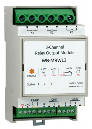
Three-channel relay modules WB-MRWL3 are used in industrial and home automation systems. They are intended for commutation of powerful power load of General purpose, including inductive: control of groups of sockets, engines, heaters, etc.
WB-MRWL3 modules are designed for rated load up to 20A (4.5 kW) per channel and can be used directly without intermediate contactors for switching outlet groups and other loads protected by an automatic switch with a nominal value of 16A.
WB-MRWL3 hass an input that simultaneously deactivates all the load.
Outputs
The module has three independent normally-open relay outputs.
Relays are certified only for use on alternating current, the load capacity of the DC may be lower. Each relay contact is protected from arcing when the varistor closes/opens. Depending on the Modbus register settings, the state of the inputs can be resumed after a power interruption (see #Relay operation mode in case of power loss). The table below lists the technical characteristics of the relays used in the module.
Relay parameters
Our detailed article in Russian on habr.com about the choice of relay parameters for the switched load: https://habr.com/ru/company/wirenboard/blog/422197/
| Maximum switching current,
resistive load 230V AC |
20A |
| Maximum allowable inrush current
(within 20ms, for no contact) |
30A |
| Contact resistance | < 100 milliohms |
| Contact material | AgSnO2 |
| Contact configuration | SPST (NO, COM) |
| Lifetime: number of switches
for load 20A 230V AC, cos φ = 1 |
30 000 |
| Lifetime: number of switches
without load |
1 000 000 |
| Relay model | Hongfa HF161F-W |
| Peculiar properties | High current |
| Application | General purpose power load, inductive load. |
Inputs
The inputs of the WB-MRWL3 modules are led out on detachable screw terminals. Inputs are organized on the dry contact principle. Buttons or switches are connected between the corresponding inputs and iGND inputs.
The 3 inputs can be used for direct control of the respective relay channels. Another input can be used for group disconnection of all channels.
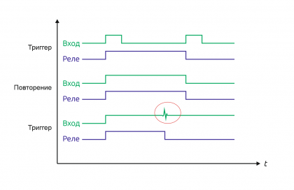
The inputs have two modes of operation: trigger mode (for control with buttons) and repeat mode (for control with switches). In the trigger mode, to change the state of the relay, it is enough to close and open the input once. The change of state occurs on the rising edge (that is, when the circuit). In the repeat mode, the relay state is determined by the input state: the input is closed — the relay is on, open — off. Details about the mode switching written in Modbus Management Of Relay Modules.
IMPORTANT: it is not recommended to use switches (lock buttons) in the trigger mode of inputs. Input interference may be perceived as a short release/push of the button and the relay status will change, although the switch will remain closed.
Technical specifications
| Parameter | Value |
|---|---|
| Power | |
| Supply voltage | 12 — 28 V DC |
| Power consumption |
|
| Terminals and wire section | |
| Recommended wire cross-section with NSUI, mm2 | 0,75 — 1 for control inputs, 2 x 2.5 for relay outputs |
| Length of the standard sleeve NSVE, mm | 8 (10 for relay outputs) |
| Torque of screws, N∙m | 0,2 for control inputs , 0,4 — for power outputs |
| Outputs | |
| Output type | Mechanical relay contacts |
| Output configuration | 3 / output connected to the relay contacts |
| Configuration of each output contacts | Two-position, normally open (S and NO) |
| Maximum switching voltage, AC | 250 V |
| Maximum switching voltage, DC | 30 Volts |
| Rated current per channel | 20 A |
| Contact resistance | < 100 milliohms |
| Voltage isolation between the controller and the output | 1500 V (RMS value) |
| Term life: | see table in #Relay parameters |
| Inputs | |
| Number of inputs (Inputs 0—3) | 4 (3+1) |
| Input type | "Dry contact", group insulation.
The input voltage is ~4.5 V. Current closing input ~2mA. |
| Functions |
|
| Control | |
| Management interface | RS-485 |
| Interface isolation | Uninsulated |
| Communication protocol | Modbus RTU, the address is set by software, factory settings are indicated on the label |
| RS-485 interface parameters | set programmatically (see register card); default: speed — 9600 bit/s; data — 8 bit; parity bit — none (N); stop bits — 2 |
| Ready for operation after power supply | ~0.03 c |
| dimensions | |
| Width, DIN units | 3 |
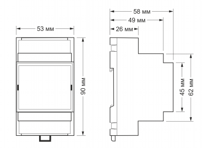
| Overall dimensions (l x W x h) | 53.3 x 90.2 x 57.5 mm |
| Display | |
| Power and data exchange indication | Green status led |
| Relay channel status indication | Red LEDs, 1 — 3 |
| Operating conditions | |
| Air temperature | |
| Relative humidity | Up to 85%, without condensation |
Габаритные размеры модулей
Installation of modules
The relay module is mounted on a standard 35 mm wide DIN rail and occupies a width of 3 DIN modules.
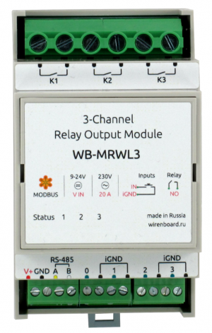
All connections are realized by blocks of screw clips. The wire section for contacts K1 — K3 must correspond to the switched load.
When connecting the switching devices to the relay contacts K1 — K3, it is important not to exceed the recommended current — 20 A.
The flowing current is small when the button or switch is closed, so the button or switch can be any type. Despite the built-in protection against rattle, choose quality buttons and switches to avoid false alarms due to bad contacts.
If the device is the last one on the RS-485 line, a 120 Ohm resistor-terminator must be installed between its inputs A and B. Practice shows that in the case of bench tests with a small length of the RS-485 line and a small number of terminator devices on the last device in the line can be installed without terminator.
The module must be installed in such a way as to meet the requirements of electrical safety and to prevent accidental contact of contacts under high voltage. The module must be operated under recommended environmental conditions.
Relay operation in case of power failure
Depending on the value written to the storage register 0x06, after the power is turned off and restored, the relays will remain off (if the value is 0, or turn on those that were turned on before the power interruption if the register has a value of 1).
Modbus Control
Details of the work with the module via Modbus Protocol is written in Relay Modules Modbus Management . There you can also find a map of the device registers.
Back to peripheral devices list
Device firmware update
Starting with the new firmware versions of the device, the firmware update functionality (firmware) via the Modbus Protocol is supported. This makes it possible to extend the functionality of the devices and eliminate errors in the firmware directly at the installation site. Read more about flashing devices described in the article Download firmware to Wiren Board devices. A list of firmware versions that support the update, as well as devices for which this feature is implemented, can be found in Firmware Changelog.
Known faults and bugs
Images and drawings of the device
По ссылкам ниже вы можете скачать изображения и чертежи устройства WB-MRWL3.
Corel Draw 2018: WB-MRWL3.cdr.zip
Corel Draw PDF: WB-MRWL3.cdr.pdf
Autocad 2013 DXF: WB-MRWL3.dxf.zip
Autocad PDF: WB-MRWL3.pdf


