WBE2-DO-OC-2 Open Collector Outputs Extension Module/en: различия между версиями
(Новая страница: «==Configuration==») |
(Новая страница: « Configuration is carried out in the web interface, section Configs => Hardware Modules Configuration.») |
||
| Строка 72: | Строка 72: | ||
==Configuration== | ==Configuration== | ||
Configuration is carried out in the web interface, section Configs => Hardware Modules Configuration. | |||
В разделе Internal slot 1 или 2 (в зависимости от номера слота) выбрать "WBE2-DO-OC-2: Dual Open-Collector Output Module" и нажать Save. | В разделе Internal slot 1 или 2 (в зависимости от номера слота) выбрать "WBE2-DO-OC-2: Dual Open-Collector Output Module" и нажать Save. | ||
Версия 12:26, 27 июня 2019
The module is designed to control the inputs of the "dry contact" type, as well as for switching low-voltage load in tasks where galvanic isolation is required.
Technical specifications
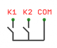
The module contains two N-channel transistors with common ground.
Each channel has built-in protection against voltage surges when switching inductive load (TVS at 30V).
The ground (GND) of the load must be connected to the GND terminal of the module (O3 terminal of the extension module).
| Parameter | Value |
|---|---|
| Number of outputs | 2 |
| Outputs type | N-channel field effect transistor
(open collector) |
| Contact configuration | SPST (normally open) |
| Maximum switching voltage | 40V DC |
| Maximum switching current, per channel | 1A |
| The channel resistance in the open state | 200 mOhm |
| Voltage isolation between the controller and the output | no |
| Maximum power consumption | 0.01 W |
| Compatibility | Compatiblу with Wiren Board 6 of all revisions. |
Pinout
| Terminal | Function |
|---|---|
| O1 | K1 |
| O2 | K2 |
| O3 | GND |
Configuration
Configuration is carried out in the web interface, section Configs => Hardware Modules Configuration.
В разделе Internal slot 1 или 2 (в зависимости от номера слота) выбрать "WBE2-DO-OC-2: Dual Open-Collector Output Module" и нажать Save.
После добавления два дополнительных выхода появляется в Devices рядом с выходами контроллера (раздел Discrete I/O).
При добавлении устройство определяется сразу же, перезагрузка не требуется.
MQTT
| Слот | Клемма | Выход | Канал (MQTT) | Топик (MQTT) |
|---|---|---|---|---|
| MOD1 | O1 | K1 | wb-gpio/MOD1_K1 | /devices/wb-gpio/controls/MOD1_K1 |
| O2 | K2 | wb-gpio/MOD1_K2 | /devices/wb-gpio/controls/MOD1_K2 | |
| MOD2 | O1 | K1 | wb-gpio/MOD2_K1 | /devices/wb-gpio/controls/MOD2_K1 |
| O2 | K2 | wb-gpio/MOD2_K2 | /devices/wb-gpio/controls/MOD2_K2 |
Порядок подключения
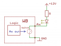
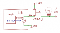
Нагрузка подключается следующим образом: "плюс" нагрузки подключается к источнику питания, "минус" подключается к транзисторному выходу. Чтобы нагрузка начала работать, нужно подать высокий уровень на затвор транзистора.
На иллюстрациях приведены схемы подключения светодиода и реле.
