WBIO-DO-HS-8 Discrete Outputs/en: различия между версиями
(Новая страница: «==Technical specifications==») |
FuzzyBot (обсуждение | вклад) (Часть переводимой страницы Модуль дискретных выходов (WBIO-DO-HS-8).) |
||
| (не показано 12 промежуточных версий 2 участников) | |||
| Строка 10: | Строка 10: | ||
==Technical specifications== | ==Technical specifications== | ||
Contains 8 outputs such as "High Side Switch" - when you turn on channel Vin voltage is supplied to the output. | |||
The module is based on [http://www.infineon.com/dgdl/Infineon-BTS4880R-DS-v01_02-EN.pdf?fileId=5546d4625a888733015aa9afa1f635cd BTS4880R] chip. | |||
The outputs are protected against overload, short circuit, overheating, spikes when controlling the inductive load. | |||
{| class="wikitable" | {| class="wikitable" | ||
! | !Parameter | ||
! | !Value | ||
|- | |- | ||
| | |Number of outputs | ||
|8 | |8 | ||
|- | |- | ||
| | |Number of groups | ||
|1 | |1 | ||
|- | |- | ||
| | |Output type | ||
|High Side Switch | |High Side Switch | ||
|- | |- | ||
| | |Switching voltage | ||
|11 - 45 V DC | |11 - 45 V DC | ||
|- | |- | ||
| | |Maximum switching current, per channel | ||
|0.6 A | |0.6 A | ||
|- | |- | ||
| | |Leakage current disabled output (each output) | ||
|<10 | |<10 µa | ||
|- | |- | ||
| | |The channel resistance in the open state | ||
|200 mOhm | |200 mOhm | ||
|- | |- | ||
| | |Module type | ||
|O (non-inverted addr.) | |O (non-inverted addr.) | ||
|- | |- | ||
| | |Maximum power consumption | ||
|0.025 | |0.025 W | ||
|- | |- | ||
| | |Width, DIN units | ||
|2 | |2 | ||
|- | |- | ||
| | |Size | ||
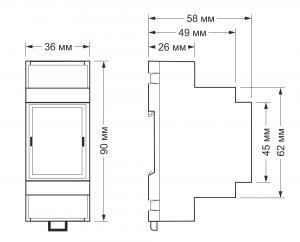
|36.3x90.2x57.5 mm | |36.3x90.2x57.5 mm | ||
|} | |} | ||
{| class="wikitable" | {| class="wikitable" | ||
!colspan="2" | ''' | !colspan="2" | '''Terminals and wire section''' | ||
|- | |- | ||
|| | || Recommended wire cross-section with TSVI, mm<sup>2</sup>|| 0,75 — 1 | ||
|- | |- | ||
|| | || Length of the standard sleeve NSVE, mm || 8 (10 for adjusting screwless terminal blocks) | ||
|- | |- | ||
|| | || Torque of screws, N∙m || 0,2 (for screw terminals) | ||
|- | |- | ||
|} | |} | ||
[[File:DIN 2U.png |300px|thumb|right| | [[File:DIN 2U.png |300px|thumb|right|Dimensions]] | ||
== | == Connection to the controller == | ||
See [[Модули ввода-вывода/en#Activating the modules in the controller web interface|Activating the modules in the web interface of the controller]] | |||
== | == Load connection== | ||
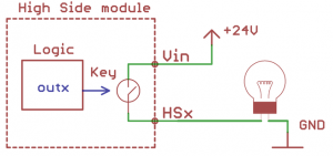
the module requires an external power supply to the terminals '''Vin''' and '''GND''' (11 to 45V). | |||
The ground of the module must be connected to the ground of the controller! | |||
[[Файл:HSx.png|300px|thumb|none| | [[Файл:HSx.png|300px|thumb|none| High Side Outputs working scheme ]] | ||
== | == Device images and drawings == | ||
{{Wbincludes:WBPicturesNoDrawing|1}} | {{Wbincludes:WBPicturesNoDrawing|1}} | ||
Текущая версия на 13:04, 22 апреля 2021
Purpose
The module is designed to control low-voltage loads: relays, low-voltage motors, signal lamps, etc
Technical specifications
Contains 8 outputs such as "High Side Switch" - when you turn on channel Vin voltage is supplied to the output.
The module is based on BTS4880R chip.
The outputs are protected against overload, short circuit, overheating, spikes when controlling the inductive load.
| Parameter | Value |
|---|---|
| Number of outputs | 8 |
| Number of groups | 1 |
| Output type | High Side Switch |
| Switching voltage | 11 - 45 V DC |
| Maximum switching current, per channel | 0.6 A |
| Leakage current disabled output (each output) | <10 µa |
| The channel resistance in the open state | 200 mOhm |
| Module type | O (non-inverted addr.) |
| Maximum power consumption | 0.025 W |
| Width, DIN units | 2 |
| Size | 36.3x90.2x57.5 mm |
| Terminals and wire section | |
|---|---|
| Recommended wire cross-section with TSVI, mm2 | 0,75 — 1 |
| Length of the standard sleeve NSVE, mm | 8 (10 for adjusting screwless terminal blocks) |
| Torque of screws, N∙m | 0,2 (for screw terminals) |
Connection to the controller
See Activating the modules in the web interface of the controller
Load connection
the module requires an external power supply to the terminals Vin and GND (11 to 45V).
The ground of the module must be connected to the ground of the controller!
Device images and drawings
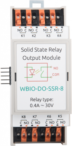
По ссылкам ниже вы можете скачать изображения и чертежи устройства WBIO-DO-SSR-8.
Corel Draw 2018: WBIO-DO-SSR-8.cdr.zip
Corel Draw PDF: WBIO-DO-SSR-8.cdr.pdf
Autocad 2013 DXF: Мы еще не подготовили чертеж этого устройства. Вы можете запросить чертеж устройства "Digital output module WBIO-DO-SSR-8" на портале техподдержки Wiren Board (необходима регистрация).


