WBIO-DO-R10R-4 Relay Module For Roller Shutter/en: различия между версиями
(Новая страница: «250px|thumb|right| WBIO-DO-R10R-4 ») |
FuzzyBot (обсуждение | вклад) (Часть переводимой страницы Модуль релейных выходов 10A (roller shutter) (WBIO-DO-R10R-4).) |
||
| (не показано 20 промежуточных версий 2 участников) | |||
| Строка 5: | Строка 5: | ||
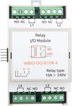
[[Файл:WBIO-DO-R10R-4.png|250px|thumb|right| WBIO-DO-R10R-4 ]] | [[Файл:WBIO-DO-R10R-4.png|250px|thumb|right| WBIO-DO-R10R-4 ]] | ||
== | ==Purpose== | ||
Control of electric curtains, shutters, shutoff valves. | |||
== | ==Technical specifications== | ||
Contains 4 relay groups. | |||
Each group has three possible states. | |||
{| class="wikitable" | {| class="wikitable" | ||
! | !Parameter | ||
! | !Value | ||
|- | |- | ||
| | |Number of output groups | ||
|4 | |4 | ||
|- | |- | ||
| | |Output type | ||
| | |mechanical relay | ||
|- | |- | ||
| | |Contact configuration | ||
|SPCO/ | |SPCO/all sptt (see scheme) | ||
output group states: | |||
* | * off, | ||
* | * LX and NC closed, | ||
* | * Lx and NO closed | ||
|- | |- | ||
| | |Maximum switching voltage, AC | ||
|250 | |250 V | ||
|- | |- | ||
| | |Maximum switching voltage, DC | ||
|30 | |30 Volts | ||
|- | |- | ||
| | |Maximum switching current, per channel (*) | ||
|3 | |3 A | ||
|- | |- | ||
| | |The channel resistance in the open state | ||
|< 100 mOhm | |< 100 mOhm | ||
|- | |- | ||
| | |Voltage isolation between the controller and the output | ||
|1500 | |1500 V (RMS.) | ||
|- | |- | ||
| | |Lifetime: number of switches | ||
for 10 A 230 V AC load, cos φ = 1 | |||
|100 000 | |100 000 | ||
|- | |- | ||
| | |Module type | ||
|"O" (non-inverted address scheme) | |"O" (non-inverted address scheme) | ||
|- | |- | ||
| | |Maximum power consumption | ||
|1 | |1 W | ||
|- | |- | ||
| | |Width, DIN units | ||
|3 | |3 | ||
|- | |- | ||
| | |Size | ||
|53,3x90,2x57,5 | |53,3x90,2x57,5 mm | ||
|} | |} | ||
<nowiki>*</nowiki>) | <nowiki>*</nowiki>) Maximum switching current is specified for 230 VAC resistive load. | ||
{| class="wikitable" | {| class="wikitable" | ||
!colspan="2" | ''' | !colspan="2" | '''Terminals and wire section''' | ||
|- | |- | ||
|| | || The recommended wire cross section with pin bushing insulated tip, mm<sup>2</sup> || 2,5 | ||
|- | |- | ||
|| | || Standard sleeve length of pin bushing insulated tip, mm || 8 | ||
|- | |- | ||
|| | ||Tightening torque of screws, Н∙м || 0,5 | ||
|- | |- | ||
|} | |} | ||
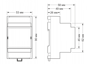
[[File:DIN 3U.png |300px|thumb|right| | [[File:DIN 3U.png |300px|thumb|right|Dimensions]] | ||
== | == Connection to the controller == | ||
== Connection to the controller == | |||
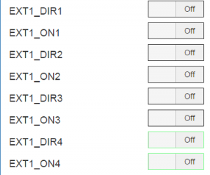
See [[Модули ввода-вывода/en#Activating the modules in the controller web interface|Activating the modules in the web interface of the controller]]. In the Discrete I/O device, EXT(1-8)_DIR(1-4) and EXT(1-8)_ON(1-4) controls will be created after the module connection. DIR controls are responsible for direction selection (relay R2 on the circuit), and ON controls are responsible for switching on and off (relay R1 on the circuit). These controls in MQTT messages are called /devices/wb-gpio/controls/EXT'''x'''_DIR'''y''' and /devices/wb-gpio/controls/EXT'''x'''_ON'''y'''. | |||
[[File:WBIO-DO-R10R-4-controls.png|300px|thumb|right| | [[File:WBIO-DO-R10R-4-controls.png|300px|thumb|right|Module's controls in the web interface]] | ||
== | == Module outputs — load connection== | ||
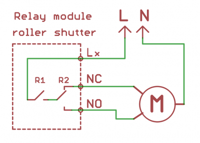
The phase wire is connected to the Lx terminals. Both terminals of the Lx contact group are connected on the board. NC and NO terminals are connected to the engine, setting the direction of rotation. The NO and NC outputs are protected by varistors. | |||
[[Файл:Roll.png|400px|thumb|none| | [[Файл:Roll.png|400px|thumb|none| Wiring diagram of the engine to the WBIO-DO-R10R-4 module]] | ||
== | == Images and drawings of the device == | ||
{{Wbincludes:WBPictures|1}} | {{Wbincludes:WBPictures|1}} | ||
Текущая версия на 12:51, 22 апреля 2021
Purpose
Control of electric curtains, shutters, shutoff valves.
Technical specifications
Contains 4 relay groups.
Each group has three possible states.
| Parameter | Value |
|---|---|
| Number of output groups | 4 |
| Output type | mechanical relay |
| Contact configuration | SPCO/all sptt (see scheme)
output group states:
|
| Maximum switching voltage, AC | 250 V |
| Maximum switching voltage, DC | 30 Volts |
| Maximum switching current, per channel (*) | 3 A |
| The channel resistance in the open state | < 100 mOhm |
| Voltage isolation between the controller and the output | 1500 V (RMS.) |
| Lifetime: number of switches
for 10 A 230 V AC load, cos φ = 1 |
100 000 |
| Module type | "O" (non-inverted address scheme) |
| Maximum power consumption | 1 W |
| Width, DIN units | 3 |
| Size | 53,3x90,2x57,5 mm |
*) Maximum switching current is specified for 230 VAC resistive load.
| Terminals and wire section | |
|---|---|
| The recommended wire cross section with pin bushing insulated tip, mm2 | 2,5 |
| Standard sleeve length of pin bushing insulated tip, mm | 8 |
| Tightening torque of screws, Н∙м | 0,5 |
Connection to the controller
Connection to the controller
See Activating the modules in the web interface of the controller. In the Discrete I/O device, EXT(1-8)_DIR(1-4) and EXT(1-8)_ON(1-4) controls will be created after the module connection. DIR controls are responsible for direction selection (relay R2 on the circuit), and ON controls are responsible for switching on and off (relay R1 on the circuit). These controls in MQTT messages are called /devices/wb-gpio/controls/EXTx_DIRy and /devices/wb-gpio/controls/EXTx_ONy.
Module outputs — load connection
The phase wire is connected to the Lx terminals. Both terminals of the Lx contact group are connected on the board. NC and NO terminals are connected to the engine, setting the direction of rotation. The NO and NC outputs are protected by varistors.
Images and drawings of the device
По ссылкам ниже вы можете скачать изображения и чертежи устройства WBIO-DO-R10R-4.
Corel Draw 2018: WBIO-DO-R10R-4.cdr.zip
Corel Draw PDF: WBIO-DO-R10R-4.cdr.pdf
Autocad 2013 DXF: WBIO-DO-R10R-4.dxf.zip
Autocad PDF: WBIO-DO-R10R-4.pdf


