WBIO-DO-R1G-16 1A Relay Module/en: различия между версиями
(Новая страница: «*off. *Kx and NO closed») |
(Новая страница: «|- |Maximum switching voltage, alternating current |250 V |- |Maximum switching voltage, direct current |30 Volts |- |Maximum switching current, per channel (*) |…») |
||
| Строка 39: | Строка 39: | ||
|- | |- | ||
| | |Maximum switching voltage, alternating current | ||
|250 | |250 V | ||
|- | |- | ||
| | |Maximum switching voltage, direct current | ||
|30 | |30 Volts | ||
|- | |- | ||
| | |Maximum switching current, per channel (*) | ||
|5 | |5 A | ||
|- | |- | ||
| | |Maximum switching current, | ||
the channels in one group | |||
|10 | |10 A | ||
|- | |- | ||
| | |The channel resistance in the open state | ||
|< 50 | |< 50 mW | ||
|- | |- | ||
| | |Voltage isolation between the controller and the output | ||
|2000 | |2000 V (RMS.) | ||
|- | |- | ||
| | |Lifetime: number of switches | ||
for load 3 A 230 V AC, cos φ = 1 | |||
|100 000 | |100 000 | ||
|- | |- | ||
| | |Lifetime: number of switches | ||
for load 0.1 A 230 V AC, cos φ = 1 (**) | |||
|1 000 000 | |1 000 000 | ||
|- | |- | ||
| | |Module type | ||
|"O" (non-inverted address scheme) | |"O" (non-inverted address scheme) | ||
|- | |- | ||
| | |Maximum power consumption | ||
|1 | |1 W | ||
|- | |- | ||
| | |Width, DIN units | ||
|3 | |3 | ||
|- | |- | ||
| | |Size | ||
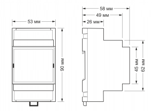
|53,3x90,2x57,5 | |53,3x90,2x57,5 mm | ||
|} | |} | ||
Версия 16:33, 15 июля 2019
Purpose
Control of contactors, warning lights, etc.
Technical specifications
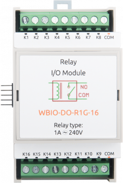
Contains 16 HF49FD relays [(Datasheet)] with the configuration of contacts SPST (two contacts on the relay: NO/COM).
The relays are combined into two groups of 8 pieces, each group has one common COM pin: the upper COM pin for relays K1 — K8 and the lower COM pin for relays K9 — K16. There's no connection between groups, so the first group can switch one voltage source, and the second - the other.
Rated channel current: 1 A. The module has protection against sparking of the contacts.
Our detailed article in russian on habr.com about the choice of relay parameters for the switched load: https://habr.com/ru/company/wirenboard/blog/422197/
| Parameter | Value |
|---|---|
| Number of outputs | 16 |
| Number of output groups | 2 |
| Output type | mechanical relay |
| Contact configuration | SPST, normally open
states:
|
| Maximum switching voltage, alternating current | 250 V |
| Maximum switching voltage, direct current | 30 Volts |
| Maximum switching current, per channel (*) | 5 A |
| Maximum switching current,
the channels in one group |
10 A |
| The channel resistance in the open state | < 50 mW |
| Voltage isolation between the controller and the output | 2000 V (RMS.) |
| Lifetime: number of switches
for load 3 A 230 V AC, cos φ = 1 |
100 000 |
| Lifetime: number of switches
for load 0.1 A 230 V AC, cos φ = 1 (**) |
1 000 000 |
| Module type | "O" (non-inverted address scheme) |
| Maximum power consumption | 1 W |
| Width, DIN units | 3 |
| Size | 53,3x90,2x57,5 mm |
*) Максимальный коммутируемый ток указан для резистивной нагрузки 230 В переменного тока.
**) Расчётное значение
| Клеммники и сечение проводов | |
|---|---|
| Рекомендуемое сечение провода с НШВИ, мм2 | 2,5 |
| Длина стандартной втулки НШВИ, мм | 8 |
| Момент затяжки винтов, Н∙м | 0,5 |
Подключение к контроллеру
Смотрите раздел Активирование в веб-интерфейсе контроллера
Подключение нагрузки
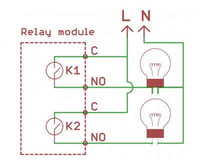
Реле подключаются в разрыв фазы.
Изображения и чертежи устройства
По ссылкам ниже вы можете скачать изображения и чертежи устройства WBIO-DO-R1G-16.
Corel Draw 2018: WBIO-DO-R1G-16.cdr.zip
Corel Draw PDF: WBIO-DO-R1G-16.cdr.pdf
Autocad 2013 DXF: WBIO-DO-R1G-16.dxf.zip
Autocad PDF: WBIO-DO-R1G-16.pdf


