WBMZ-BATTERY - модуль резервного питания/en: различия между версиями
(Новая страница: «The WBMZ battery module comes complete with the top cover of the case on which the switch is mounted. The cover is installed instead of the included controller. T…») |
(Новая страница: «One battery contact is disconnected from the module to prevent discharge during storage. Before installation it is necessary to fix the disconnected contact in a…») |
||
| Строка 117: | Строка 117: | ||
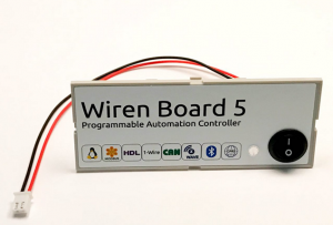
The WBMZ battery module comes complete with the top cover of the case on which the switch is mounted. The cover is installed instead of the included controller. The old cover is removed with a screwdriver inserted into the side slots between the cover and the top of the housing. | The WBMZ battery module comes complete with the top cover of the case on which the switch is mounted. The cover is installed instead of the included controller. The old cover is removed with a screwdriver inserted into the side slots between the cover and the top of the housing. | ||
One battery contact is disconnected from the module to prevent discharge during storage. Before installation it is necessary to fix the disconnected contact in a screw clip of the module (it is shown in drawing by arrows). | |||
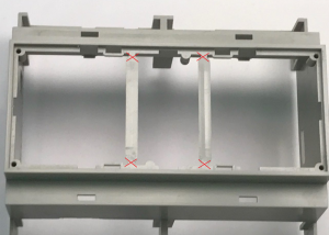
Для удобства установки модуля перемычки в верхней части корпуса можно удалить (например, кусачками). | Для удобства установки модуля перемычки в верхней части корпуса можно удалить (например, кусачками). | ||
Версия 18:14, 4 июня 2019
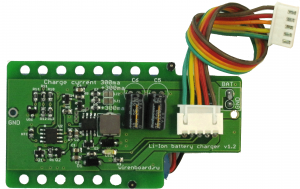
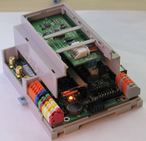
Additional mezzanine board is installed on the second level in the DIN-rail mounted controller body.
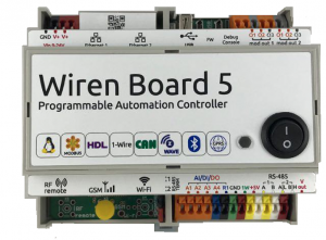
Compatible withWiren Board 5 controller. It is connected by a loop to the internal connector of the controller.
The Board contains a charge circuit Li-Ion battery with charge protection at low and high temperatures.
There is no protection against over-discharge of the connected accmulator - be sure to use batteries with built-in protection circuit.
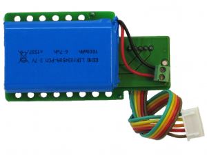
The boards are equipped with 1800 mAh batteries.
The controller receives two signals:
- STAT1 (active low) - the board is connected.
- STAT2 (active low) - the battery is charging.
Charging current is set by sealed jumpers:
- not soldered - 300 мA.
- one sealed - 600 ма.
- two sealed - 900 ма.
The standard versions:
| Package | Contents | Capacity | Weight |
|---|---|---|---|
| WBMZ-BATTERY-1800MAH | Module with LIR103450A-PCB-LD battery | 1800 mAh | 50 g |
=== Technical characteristics of the LIR103450A batteries
===
| Type | Li-ion |
| Rated voltage | 3,7 В |
| Rated capacity (C) | 1800 мАч |
| Maximum charge/discharge | 1 C |
| Charging time | 0,5 C — 5 hours
1 C — 2,5 hours; |
| charging voltage | 4,2 V |
| Operating temperature | Charge: 0°C to 45°C
Discharge: -20°C to 55°C |
| Storage temperature | |
| Charge/discharge cycles | 300 |
Connecting the module that comes with the controller
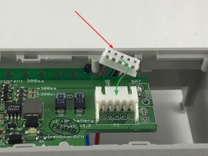
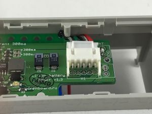
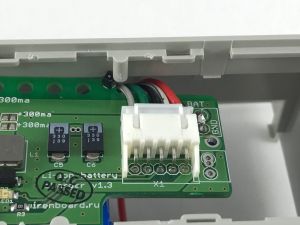
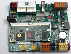
If the battery module is supplied with the controller, its connection will require minimal effort. Controllers with a battery module inside are equipped with a cover with a switch. The module itself is disconnected from the controller to avoid battery discharge. To connect the module, the cover with the switch is carefully removed with a screwdriver inserted into the side slots between the cover and the top of the housing. The switch must be connected to the connector on the controller Board. Next, you need to connect to the module loop connecting it to the board, as shown in the figures.
Replace the top cover of the controller. The controller is ready for operation.
=Connecting a module purchased separately =
Disassemble the controller body according to the instructions .
The WBMZ battery module comes complete with the top cover of the case on which the switch is mounted. The cover is installed instead of the included controller. The old cover is removed with a screwdriver inserted into the side slots between the cover and the top of the housing.
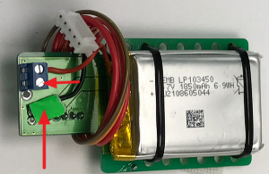
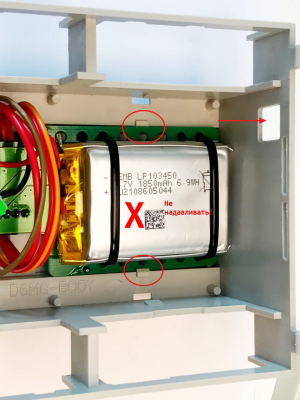
One battery contact is disconnected from the module to prevent discharge during storage. Before installation it is necessary to fix the disconnected contact in a screw clip of the module (it is shown in drawing by arrows).
Для удобства установки модуля перемычки в верхней части корпуса можно удалить (например, кусачками).
Плата модуля крепится на двух защелках (обозначены на рисунке), аккумулятором вниз, в сторону платы. Аккумулятор должен быть расположен со стороны отверстия для бокового модуля питания (показано стрелкой). Не надавливайте на аккумулятор при установке — это может привести к внутреннему короткому замыканию и возгоранию!
После установки модуля подключите разъемы к плате, как показано стрелками на рисунке "Плата контроллера с разъемами для аккумулятора и выключателя": красная стрелка — разъем выключателя, голубая — разъем модуля.
При сборке контроллера с установленным модулем обратите внимание на провода модуля: они не должны находиться между индикатором и пластиковым световодом верхней крышки корпуса контроллера. Снятие модуля производится в обратной последовательности.
