WBMZ-BATTERY - модуль резервного питания/en: различия между версиями
(Новая страница: «=== Technical characteristics of the LIR103450A batteries ===») |
(Новая страница: «When assembling the controller with the module installed, pay attention to the wires of the module: they should not be between the indicator and the plastic light…») |
||
| (не показано 13 промежуточных версий этого же участника) | |||
| Строка 52: | Строка 52: | ||
{| class="wikitable" | {| class="wikitable" | ||
| | |Type | ||
|Li-ion | |Li-ion | ||
|- | |- | ||
| | |Rated voltage | ||
|3,7 В | |3,7 В | ||
|- | |- | ||
| | |Rated capacity (C) | ||
|1800 мАч | |1800 мАч | ||
|- | |- | ||
| | |Maximum charge/discharge | ||
|1 C | |1 C | ||
|- | |- | ||
| | |Charging time | ||
|0,5 C — 5 | |0,5 C — 5 hours | ||
1 C — 2,5 | 1 C — 2,5 hours; | ||
|- | |- | ||
| | |charging voltage | ||
|4,2 | |4,2 V | ||
|- | |- | ||
| | |Operating temperature | ||
| | | Charge: 0°C to 45°C | ||
Discharge: -20°C to 55°C | |||
|- | |- | ||
| | |Storage temperature | ||
| | |-5°C to 35°C | ||
|- | |- | ||
| | |Charge/discharge cycles | ||
|300 | |300 | ||
|} | |} | ||
= | =Connecting the module that comes with the controller= | ||
[[File:Wb58withswitch.png|300px|thumb|right| | [[File:Wb58withswitch.png|300px|thumb|right| | ||
Switch on the top cover of the controller]] | |||
If the battery module is supplied with the controller, its connection will require minimal effort. Controllers with a battery module inside are equipped with a cover with a switch. The module itself is disconnected from the controller to avoid battery discharge. To connect the module, the cover with the switch is carefully removed with a screwdriver inserted into the side slots between the cover and the top of the housing. The switch must be connected to the connector on the controller Board. Next, you need to connect to the module loop connecting it to the board, as shown in the figures. | |||
{| class="wikitable" | {| class="wikitable" | ||
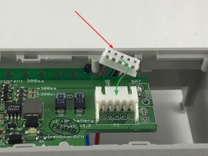
! [[File:Withbattery1.jpg|300px|thumb|left| | ! [[File:Withbattery1.jpg|300px|thumb|left|Initially, the loop connector is not connected to the module | ||
! [[File:Withbattery2.jpg|300px|thumb|center| | ]] | ||
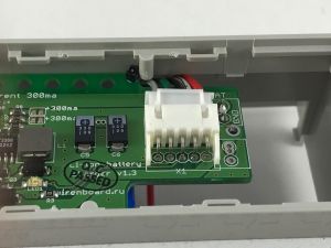
! [[File:Withbattery3.jpg|300px|thumb|right| | ! [[File:Withbattery2.jpg|300px|thumb|center|Insert the plug of the loop | ||
]] | |||
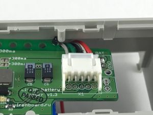
! [[File:Withbattery3.jpg|300px|thumb|right|And push inside the connector until it stops]] | |||
|} | |} | ||
Replace the top cover of the controller. The controller is ready for operation. | |||
= | =Connecting a module purchased separately | ||
= | |||
<!--полная последовательность действий при установке [[WBMZ-BATTERY_-_модуль_резервного_питания|батарейного модуля WBMZ-BATTERY]]. Она выполняется в том случае, если аккумуляторный модуль был приобретен отдельно от контроллера. Если модуль приобретался в коплекте с контроллером, то вам необходимо будет подключить шлейф модуля и контакт аккумулятора, открыв только верхнюю крышку. Подробнее смотрите раздел [[#подключаем-аккумуляторный модуль|Подключаем аккумуляторный модуль]]. | <!--полная последовательность действий при установке [[WBMZ-BATTERY_-_модуль_резервного_питания|батарейного модуля WBMZ-BATTERY]]. Она выполняется в том случае, если аккумуляторный модуль был приобретен отдельно от контроллера. Если модуль приобретался в коплекте с контроллером, то вам необходимо будет подключить шлейф модуля и контакт аккумулятора, открыв только верхнюю крышку. Подробнее смотрите раздел [[#подключаем-аккумуляторный модуль|Подключаем аккумуляторный модуль]]. | ||
--> | --> | ||
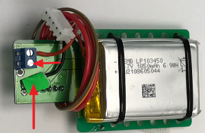
[[File:Battery_Module.png|300px|thumb|left| | [[File:Battery_Module.png|300px|thumb|left|Battery module, one battery contact disconnected | ||
[[File:Top_cover_with_switch.png|300px|thumb|right| | ]] | ||
[[File:Junctions.png|300px|thumb|right| | [[File:Top_cover_with_switch.png|300px|thumb|right|The top cover of the controller enclosure with a switch | ||
[[File:The_mainboard.png|300px|thumb|left| | ]] | ||
[[File:Junctions.png|300px|thumb|right|The jumpers under the top cover can be removed | |||
]] | |||
[[File:The_mainboard.png|300px|thumb|left|Controller board with battery and switch connectors | |||
]] | |||
''' | '''Disassemble the controller body according to the [[Разбираем_корпус_контроллера/en| instructions ]].''' | ||
The WBMZ battery module comes complete with the top cover of the case on which the switch is mounted. The cover is installed instead of the included controller. The old cover is removed with a screwdriver inserted into the side slots between the cover and the top of the housing. | |||
One battery contact is disconnected from the module to prevent discharge during storage. Before installation it is necessary to fix the disconnected contact in a screw clip of the module (it is shown in drawing by arrows). | |||
For the convenience of installing the jumper module in the upper part of the body can be removed (for example, wire cutters). | |||
[[File:Battery latches.png|300px|thumb|center| | [[File:Battery latches.png|300px|thumb|center|Module mounting]] | ||
The module Board is mounted on two latches (indicated in the figure), the battery down to the side of the Board. The battery should be located on the side of the side power module opening (shown by arrow). Do not apply pressure to the battery during installation — this may cause an internal short circuit and fire! | |||
After installing the module, connect the connectors to the Board, as shown by the arrows in the figure "controller Board with battery and switch connectors": red arrow — switch connector, blue — module connector. | |||
When assembling the controller with the module installed, pay attention to the wires of the module: they should not be between the indicator and the plastic light guide of the upper cover of the controller body. Removal of the module is made in the reverse order. | |||
Текущая версия на 18:14, 4 июня 2019
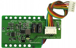
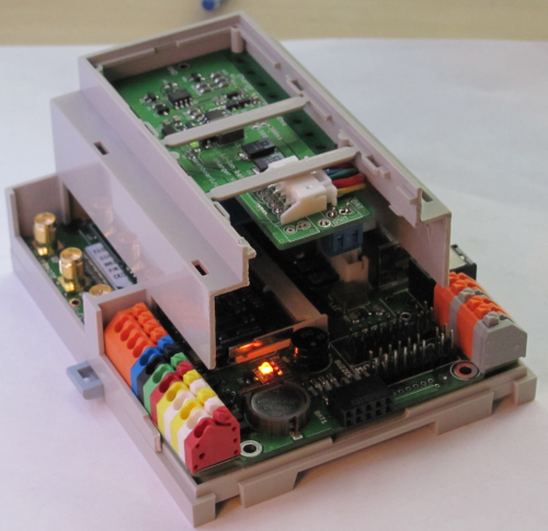
Additional mezzanine board is installed on the second level in the DIN-rail mounted controller body.
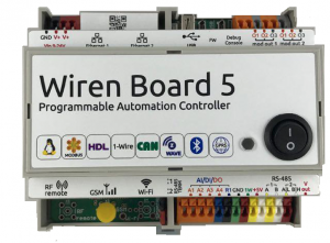
Compatible withWiren Board 5 controller. It is connected by a loop to the internal connector of the controller.
The Board contains a charge circuit Li-Ion battery with charge protection at low and high temperatures.
There is no protection against over-discharge of the connected accmulator - be sure to use batteries with built-in protection circuit.
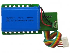
The boards are equipped with 1800 mAh batteries.
The controller receives two signals:
- STAT1 (active low) - the board is connected.
- STAT2 (active low) - the battery is charging.
Charging current is set by sealed jumpers:
- not soldered - 300 мA.
- one sealed - 600 ма.
- two sealed - 900 ма.
The standard versions:
| Package | Contents | Capacity | Weight |
|---|---|---|---|
| WBMZ-BATTERY-1800MAH | Module with LIR103450A-PCB-LD battery | 1800 mAh | 50 g |
=== Technical characteristics of the LIR103450A batteries
===
| Type | Li-ion |
| Rated voltage | 3,7 В |
| Rated capacity (C) | 1800 мАч |
| Maximum charge/discharge | 1 C |
| Charging time | 0,5 C — 5 hours
1 C — 2,5 hours; |
| charging voltage | 4,2 V |
| Operating temperature | Charge: 0°C to 45°C
Discharge: -20°C to 55°C |
| Storage temperature | |
| Charge/discharge cycles | 300 |
Connecting the module that comes with the controller
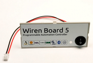
If the battery module is supplied with the controller, its connection will require minimal effort. Controllers with a battery module inside are equipped with a cover with a switch. The module itself is disconnected from the controller to avoid battery discharge. To connect the module, the cover with the switch is carefully removed with a screwdriver inserted into the side slots between the cover and the top of the housing. The switch must be connected to the connector on the controller Board. Next, you need to connect to the module loop connecting it to the board, as shown in the figures.
Replace the top cover of the controller. The controller is ready for operation.
=Connecting a module purchased separately =
Disassemble the controller body according to the instructions .
The WBMZ battery module comes complete with the top cover of the case on which the switch is mounted. The cover is installed instead of the included controller. The old cover is removed with a screwdriver inserted into the side slots between the cover and the top of the housing.
One battery contact is disconnected from the module to prevent discharge during storage. Before installation it is necessary to fix the disconnected contact in a screw clip of the module (it is shown in drawing by arrows).
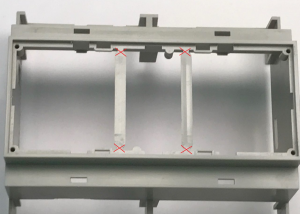
For the convenience of installing the jumper module in the upper part of the body can be removed (for example, wire cutters).
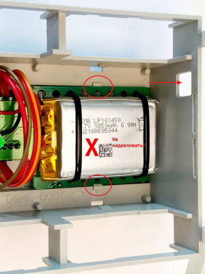
The module Board is mounted on two latches (indicated in the figure), the battery down to the side of the Board. The battery should be located on the side of the side power module opening (shown by arrow). Do not apply pressure to the battery during installation — this may cause an internal short circuit and fire!
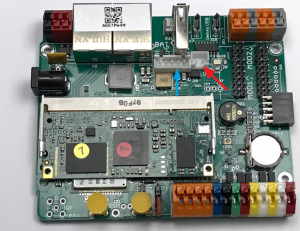
After installing the module, connect the connectors to the Board, as shown by the arrows in the figure "controller Board with battery and switch connectors": red arrow — switch connector, blue — module connector.
When assembling the controller with the module installed, pay attention to the wires of the module: they should not be between the indicator and the plastic light guide of the upper cover of the controller body. Removal of the module is made in the reverse order.
