Wb-mqtt-serial templates/en: различия между версиями

Материал из Wiren Board
(Новая страница: «<syntaxhighlight lang="JSON"> "channels": [ { "name": "Channel name1", ... }, { "name": "Channel name2…»)
(Новая страница: «The structure contains the following set of fields.»)
Строка 73: Строка 73:
</syntaxhighlight>
</syntaxhighlight>


Структура содержит следующий набор полей.
The structure contains the following set of fields.


[[File:Vartype_properties_mqtt_serial.png|450px|thumb|right|формат представления данных в Modbus-регистрах, описывается в wb-mqtt-serial.schema.json (подготовлено в [http://www.bodurov.com/JsonFormatter/ Collapsible JSON Formatter])]]
[[File:Vartype_properties_mqtt_serial.png|450px|thumb|right|формат представления данных в Modbus-регистрах, описывается в wb-mqtt-serial.schema.json (подготовлено в [http://www.bodurov.com/JsonFormatter/ Collapsible JSON Formatter])]]

Версия 16:12, 11 июня 2019

Другие языки:

=== The general structure of the device template

===

A device template file is a JSON structure that describes device parameters. The template allows comments. The JSON structure is written inside the space between the opening and closing braces: { ... }


The general structure of the device template is as follows:

//Device template
{ 
"device": {
    "Device1 parameter":"value", 
    "Device2 parameter":"value", 
    ...
    "channels": [ {channel parameters 1}, {channel parameters 2}, ...]
    }
}

Device is a device connected to the controller, channel is a data source: usually it is a Modbus register with a description of the data type, polling frequency, value conversion, etc. See the following sections for a detailed description: template files are stored on the controller in a folder

/usr/share/wb-mqtt-serial/templates

You should copy the new templates you created for the new device to this directory. In our templates, we use indents of 4 spaces per level, which ensures the readability of the template code, and we recommend writing new templates with the same indentation.

Device settings
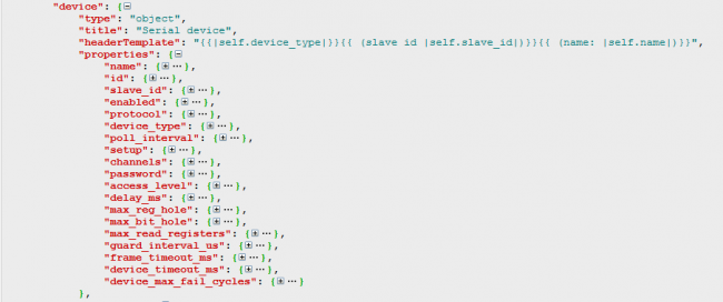
Device parameters are described in wb-mqtt-serial.schema.json (made via Collapsible JSON Formatter)

The parameters of the device are set in the form of a set of pairs key:value at the beginning of the pattern. Required parameters are "device_type" and "device" keys.

The device_type key specifies a unique name for the device type as a string, for example:

"device_type":"WB-MAP12H",

.

The device key value is a composite structure that describes specific device parameters:

"device": {
        "name": "WB-MAP12H",
        "id": "wb-map12h",
        "channels": [...]
        }


  • name — is the displayed name of the device. Published as .../meta/name in mqtt. The device name is used when displaying the web-interface, stored in the topic "id" + " " + "slave_id". Example for a device with modbus address 5 (slave_id) and value "name":"WB-MAP12H (basic)" /devices/wb-map12h_5/meta/name WB-MAP12H (basic).
  • id — is the unique identifier of the device to MQTT. Each item in devices must have a unique id. mqtt-topic related to this device in MQTT have a common prefix /devices/<topic ID>/... Also by default it is taken from the template with the addition of slave_id: "id" + "_" + slave_id


  • channels — is the list of device channels, is set as [...], each element represents a description of a particular channel.

Other device parameters are either added to the section when the template is included in the wb-mqtt-serial general configuration, or default values are used. The full list can be found in the wb-mqtt-serial.schema.json file (a copy is also stored on the controller: /usr/share/wb-mqtt-confed/schemas/wb-mqtt-serial.schema.json). See "device" object properties: "device" -> "properties".

Device channels
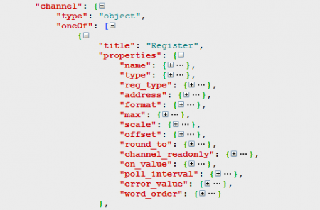
Channel parameters are described in wb-mqtt-serial.schema.json (made in app Collapsible JSON Formatter)

Channel description is a structure

"channels": [
        {
            "name": "Channel name1",
            ...
        },
        {
            "name": "Channel name2",
            ...
        },
        ...
    ]

The structure contains the following set of fields.
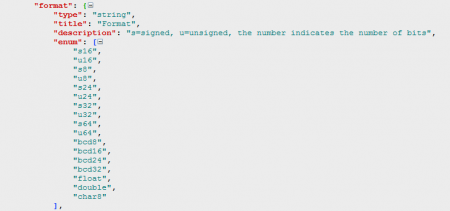
формат представления данных в Modbus-регистрах, описывается в wb-mqtt-serial.schema.json (подготовлено в Collapsible JSON Formatter)
  • name — имя канала, уникальное для устройство имя канала
  • reg_type — тип Modbus-регистра, одно из "coil", "discrete", "holding", "holding_single", "holding_multi", "input", "direct"
  • address — адрес Modbus-регистра, связанного с каналом.
  • type — тип контрола -- виртуального элемента для представления данных в Web-интерфейсе контроллера: "switch", "pushbutton", "range", "rgb" и другие; полностью перечислены в схеме wb-mqtt-serial.schema.json.
  • readonly — "true", если значения можно только считывать.
  • format — тип переменной, описывающей значение, см. рис.

В простейшем случае достаточно полей "name", "reg_type", "address" и "type". Описания остальных типов параметров полностью перечислены в схеме wb-mqtt-serial.schema.json.

Примеры шаблонов устройств

Ниже приведены примеры файлов шаблонов для некоторых устройств Wiren Board, охватывающие основной список используемых параметров при создании шаблонов.


WB-MS-THLS v.2

Устройство WB-MS-THLS — универсальный комбинированный Modbus-датчик температуры, влажности, освещённости и звукового давления. Устройство предоставляет доступ к данным через input-регистры Modbus. Первоначальные настройки устройства записаны в holding-регистры, но не используются для получения данных и управления устройством, поэтому в шаблон не входят. По ссылке "Expand" можно увидеть полный код шаблона.

{
    "device_type": "WB-MS-THLS v.2",
    "device": {
        "name": "WB-MS / WB-MSW",
        "id": "wb-ms-thls-v2",
        "max_read_registers": 0,
        "channels": [
            {
                "name": "Temperature",
                "reg_type": "input",
                "address": 0,
                "type": "temperature",
                "format": "s16",
                "scale": 0.1,
                "error_value": "0x7FFF"
            },
            {
                "name": "Humidity",
                "reg_type": "input",
                "address": 1,
                "type": "rel_humidity",
                "scale": 0.1,
                "error_value": "0xFFFF"
            },
            {
                "name": "Illuminance",
                "reg_type": "input",
                "address": 2,
                "type": "lux"
            },
            {
                "name": "Sound Level",
                "reg_type": "input",
                "address": 3,
                "scale": 0.01,
                "type": "sound_level"
            },
            {
                "name": "Input Voltage",
                "reg_type": "input",
                "address": 121,
                "scale": 0.001,
                "type": "voltage"
            },
            {
                "name": "External Sensor 1",
                "type": "temperature",
                "reg_type": "input",
                "address": "6",
                "format": "s16",
                "scale": 0.0625,
                "error_value": "0x7FFF"
            },
            {
                "name": "External Sensor 2",
                "type": "temperature",
                "reg_type": "input",
                "address": "7",
                "format": "s16",
                "scale": 0.0625,
                "error_value": "0x7FFF"
            }
        ]
    }
}

В настройках устройства интересен параметр

    "max_read_registers": 0,

Этот параметр описывает максимальное количество регистров, считываемых с устройства при запросе. Значение по умолчанию — 1, в нашем случае мы указываем считывать все регистры за один проход (bulk read).

В настройках канала "Temperature" имеются три параметра, на которые стоит обратить внимание:

    "format": "s16",
    "scale": 0.1,
    "error_value": "0x7FFF"

Параметр "format": "s16" указывает на то, что число в регистрах представлено в виде знакового 16-битного целого, "scale": 0.1 — говорит о том, что полученное из регистров значение следует домножить на коэффициент масштабирования 0,1 для получения значения температуры, а параметр "error_value": "0x7FFF" задает значение, получаемое из регистра, указывающее на то, что при опросе датчика произошла ошибка. Такой параметр будет выделен красным цветом в Web-интерфейсе контроллера. Применять такой параметр следует, если вы знаете, какое значение выдает ваше устройство в случае ошибки.


WB-MRGBW-D

Устройство WB-MRGBW-D — четырехканальный диммер для управления светодиодными лентами. Может управлять лентой RGB+W либо независимо четырьмя одноцветными лентами. Настройки яркости хранятся в holding-регистрах; шаблон описывает, какие регистры можно менять для получения нужной яркости каналов, отслеживать нажатия на кнопки диммера и получать значения количества нажатий.По ссылке "Expand" можно увидеть полный код шаблона.

{
    "device_type": "WB-MRGBW-D", 
    "device": {
        "name": "WB-MRGBW-D", 
        "id": "wb-mrgbw-d", 
        "max_read_registers": 0, 
        "channels": [
            {
                "name": "RGB", 
                "type": "rgb", 
                "consists_of": [
                    {
                        "reg_type": "holding", 
                        "address": 1
                    }, 
                    {
                        "reg_type": "holding", 
                        "address": 0
                    }, 
                    {
                        "reg_type": "holding", 
                        "address": 2
                    }
                ]
            }, 
            {
                "name": "White", 
                "reg_type": "holding", 
                "address": 3, 
                "type": "range", 
                "max": 255
            }, 
            {
                "name": "Button 1", 
                "reg_type": "holding", 
                "readonly": true, 
                "address": 6, 
                "type": "switch"
            }, 
            {
                "name": "Button 2", 
                "reg_type": "holding", 
                "readonly": true, 
                "address": 7, 
                "type": "switch"
            }, 
            {
                "name": "Button 3", 
                "reg_type": "holding", 
                "readonly": true, 
                "address": 8, 
                "type": "switch"
            }, 
            {
                "name": "Button 1 counter", 
                "reg_type": "holding", 
                "readonly": true, 
                "address": 32, 
                "type": "value"
            }, 
            {
                "name": "Button 2 counter", 
                "reg_type": "holding", 
                "readonly": true, 
                "address": 33, 
                "type": "value"
            }, 
            {
                "name": "Button 3 counter", 
                "reg_type": "holding", 
                "readonly": true, 
                "address": 34, 
                "type": "value"
            }, 
            {
                "name": "Serial NO", 
                "type": "text", 
                "reg_type": "holding", 
                "address": 270, 
                "format": "u32"
            }
        ]
    }
}

В этом шаблоне составной канал RGB задает одновременно яркости трех цветовых компонентов ленты, хранящихся в трех holding-регистрах и описывается следующим образом:

    {
        "name": "RGB", 
        "type": "rgb", 
        "consists_of": [
            {
                "reg_type": "holding", 
                "address": 1
            }, 
            {
                "reg_type": "holding", 
                "address": 0
            }, 
            {
                "reg_type": "holding", 
                "address": 2
            }
        ]
    },

Канал белого цвета управляется отдельно,

    {
        "name": "White", 
        "reg_type": "holding", 
        "address": 3, 
        "type": "range", 
        "max": 255
    },

Здесь указано максимальное значение, которое можно установить для ползунка яркости белого — 255:

"max": 255

Серийный номер устройства (канал "Serial NO") считывается как беззнаковое 32-битное целое:

"format": "u32"

WBIO-DO-R10A-8

Устройство WBIO-DO-R10A-8 — релейный боковой модуль, который подключается непосредственно к WBIO-разъему контроллера, и не управляется по Modbus. Но при подключении его через устройство расширения WB-MIO или WB-MIO-E становится полноценным Modbus-устройством, для которого имеется соответствующий шаблон. По ссылке "Expand" можно увидеть полный код шаблона.

{
    "device_type": "WBIO-DO-R10A-8",
    "device": {
        "name": "WBIO-DO-R10A-8",
        "id": "wb-mio-gpio",
        "protocol": "modbus_io",
        "stride": 1000,
        "shift": 500,
        "max_read_registers": 0,
        "setup": [
            {
                "title": "IODIR",
                "address": 10000,
                "value": "0x0000"
            },
            {
                "title": "IPOL",
                "address": 10001,
                "value": "0x0000"
            },
            {
                "title": "GPINTEN",
                "address": 10002,
                "value": "0xffff"
            },
            {
                "title": "DEFVAL",
                "address": 10003,
                "value": "0x0000"
            },
            {
                "title": "INTCON",
                "address": 10004,
                "value": "0x0000"
            },
            {
                "title": "IOCON",
                "address": 10005,
                "value": "0x4444"
            },
            {
                "title": "FLAG",
                "address": 9999,
                "value": 1
            }
        ],
        "channels": [
            {
                "name": "K1",
                "reg_type": "coil",
                "address": 0,
                "type": "switch"
            },
            {
                "name": "K2",
                "reg_type": "coil",
                "address": 1,
                "type": "switch"
            },
            {
                "name": "K3",
                "reg_type": "coil",
                "address": 2,
                "type": "switch"
            },
            {
                "name": "K4",
                "reg_type": "coil",
                "address": 3,
                "type": "switch"
            },
            {
                "name": "K5",
                "reg_type": "coil",
                "address": 4,
                "type": "switch"
            },
            {
                "name": "K6",
                "reg_type": "coil",
                "address": 5,
                "type": "switch"
            },
            {
                "name": "K7",
                "reg_type": "coil",
                "address": 6,
                "type": "switch"
            },
            {
                "name": "K8",
                "reg_type": "coil",
                "address": 7,
                "type": "switch"
            }
        ]
    }
}


В этом шаблоне следует обратить внимание на следующие параметры устройства.

    "protocol": "modbus_io",
    "stride": 1000,
    "shift": 500,
    "max_read_registers": 0,
    "setup": [

Параметр "protocol": "modbus_io" указывает, что устройство подключается оп специальному протоколу к модулю расширения. Параметры "stride": 1000 и "shift": 500 задают сдвиг регистров в зависимости от того, в каком порядке подключены модули к модулю расширения.

Сдвиг регистров (число, которое нужно добавить к базовому номеру регистра) вычисляется по формуле:

Shift = (((SlaveId.Secondary - 1) % 4) + 1) * DeviceConfig()->Stride + DeviceConfig()->Shift;

Здесь stride — DeviceConfig()->Stride, a shift — DeviceConfig()->Shift. Каждое подключенное устройство имеет порядковый номер (SlaveId.Secondary), начинающийся с 1 для первого устройства. (Здесь знаком "%" обозначается деление по модулю.) Например, подставляя значения shift и stride в формулу, получаем:

Shift = ((( 1 - 1) % 4) + 1) * 500 + 1000 = (0 + 1) * 500 + 1000 = 1500

То есть ко всем регистрам, указанным в шаблоне, надо добавить 1500.

Еще один важный параметр — setup-секция, массив

     "setup": [    {
             "title": "IODIR",
             "address": 10000,
             "value": "0x0000"
         },
     {},
     ...]

Он описывает регистры и значения, которые однократно заносятся в эти регистры при инициализации устройства (при запуске или перезапуске wb-mqtt-serial). Его можно использовать для конфигурирования устройств для работы в каком-то определенном режиме, задавать изначальные значения яркости, положения сервоприводов, состояния реле, режима работы с входами релейных модулей и т. п.


WB-MAP3H

Устройство WB-MAP3H — трехканальный счетчик электроэнергии. Он измеряет большое количество параметров электрической сети. Поскольку опрос всех регистров такого устройства может занять достаточно много времени, имеется несколько шаблонов, содержащих оптимальный набор параметров для решения текущей задачи. Мы рассмотрим базовый шаблон. По ссылке "Expand" можно увидеть полный код шаблона.

{
 "device_type": "WB-MAP3H (basic)", 
 "device": {
  "name": "WB-MAP3H (basic)", 
  "id": "wb-map3h", 
  "max_read_registers": 60, 
  "channels": [
   {
    "name": "Urms L1", 
    "reg_type": "input", 
    "address": "0x10d9", 
    "type": "voltage", 
    "format": "u16", 
    "scale": 0.01, 
    "round_to": 0.01
   }, 
   {
    "name": "THDN U L1", 
    "reg_type": "input", 
    "address": "0x10f1", 
    "type": "value", 
    "format": "u16", 
    "scale": 0.01, 
    "round_to": 0.01
   }, 
   {
    "name": "Urms L2", 
    "reg_type": "input", 
    "address": "0x10da", 
    "type": "voltage", 
    "format": "u16", 
    "scale": 0.01, 
    "round_to": 0.01
   }, 
   {
    "name": "THDN U L2", 
    "reg_type": "input", 
    "address": "0x10f2", 
    "type": "value", 
    "format": "u16", 
    "scale": 0.01, 
    "round_to": 0.01
   }, 
   {
    "name": "Urms L3", 
    "reg_type": "input", 
    "address": "0x10db", 
    "type": "voltage", 
    "format": "u16", 
    "scale": 0.01, 
    "round_to": 0.01
   }, 
   {
    "name": "THDN U L3", 
    "reg_type": "input", 
    "address": "0x10f3", 
    "type": "value", 
    "format": "u16", 
    "scale": 0.01, 
    "round_to": 0.01
   }, 
   {
    "name": "Frequency", 
    "reg_type": "input", 
    "address": "0x10f8", 
    "type": "value", 
    "format": "u16", 
    "scale": 0.01, 
    "round_to": 0.01
   }, 
   {
    "name": "Voltage angle L1", 
    "reg_type": "input", 
    "address": "0x10fd", 
    "type": "value", 
    "format": "s16", 
    "scale": 0.1, 
    "round_to": 0.01
   }, 
   {
    "name": "Voltage angle L2", 
    "reg_type": "input", 
    "address": "0x10fe", 
    "type": "value", 
    "format": "s16", 
    "scale": 0.1, 
    "round_to": 0.01
   }, 
   {
    "name": "Voltage angle L3", 
    "reg_type": "input", 
    "address": "0x10ff", 
    "type": "value", 
    "format": "s16", 
    "scale": 0.1, 
    "round_to": 0.01
   }, 
   {
    "name": "Irms L1", 
    "reg_type": "input", 
    "address": "0x10dd", 
    "type": "value", 
    "format": "u16", 
    "scale": 0.001, 
    "round_to": 0.01
   }, 
   {
    "name": "THDN I L1", 
    "reg_type": "input", 
    "address": "0x10f5", 
    "type": "value", 
    "format": "u16", 
    "scale": 0.01, 
    "round_to": 0.01
   }, 
   {
    "name": "P L1", 
    "reg_type": "input", 
    "address": "0x1302", 
    "type": "power", 
    "format": "s32", 
    "scale": 1.52588e-05, 
    "round_to": 0.01
   }, 
   {
    "name": "Q L1", 
    "reg_type": "input", 
    "address": "0x130a", 
    "type": "value", 
    "format": "s32", 
    "scale": 1.52588e-05, 
    "round_to": 0.01
   }, 
   {
    "name": "S L1", 
    "reg_type": "input", 
    "address": "0x1312", 
    "type": "value", 
    "format": "s32", 
    "scale": 1.52588e-05, 
    "round_to": 0.01
   }, 
   {
    "name": "PF L1", 
    "reg_type": "input", 
    "address": "0x10bd", 
    "type": "value", 
    "format": "s16", 
    "scale": 0.001, 
    "round_to": 0.01
   }, 
   {
    "name": "AP energy L1", 
    "reg_type": "input", 
    "address": "0x1204", 
    "type": "power_consumption", 
    "format": "u64", 
    "scale": 3.125e-05, 
    "round_to": 0.0001, 
    "word_order": "little_endian"
   }, 
   {
    "name": "RP energy L1", 
    "reg_type": "input", 
    "address": "0x1224", 
    "type": "value", 
    "format": "u64", 
    "scale": 3.125e-05, 
    "round_to": 0.0001, 
    "word_order": "little_endian"
   }, 
   {
    "name": "Irms L2", 
    "reg_type": "input", 
    "address": "0x10de", 
    "type": "value", 
    "format": "u16", 
    "scale": 0.001, 
    "round_to": 0.01
   }, 
   {
    "name": "THDN I L2", 
    "reg_type": "input", 
    "address": "0x10f6", 
    "type": "value", 
    "format": "u16", 
    "scale": 0.01, 
    "round_to": 0.01
   }, 
   {
    "name": "P L2", 
    "reg_type": "input", 
    "address": "0x1304", 
    "type": "power", 
    "format": "s32", 
    "scale": 1.52588e-05, 
    "round_to": 0.01
   }, 
   {
    "name": "Q L2", 
    "reg_type": "input", 
    "address": "0x130c", 
    "type": "value", 
    "format": "s32", 
    "scale": 1.52588e-05, 
    "round_to": 0.01
   }, 
   {
    "name": "S L2", 
    "reg_type": "input", 
    "address": "0x1314", 
    "type": "value", 
    "format": "s32", 
    "scale": 1.52588e-05, 
    "round_to": 0.01
   }, 
   {
    "name": "PF L2", 
    "reg_type": "input", 
    "address": "0x10be", 
    "type": "value", 
    "format": "s16", 
    "scale": 0.001, 
    "round_to": 0.01
   }, 
   {
    "name": "AP energy L2", 
    "reg_type": "input", 
    "address": "0x1208", 
    "type": "power_consumption", 
    "format": "u64", 
    "scale": 3.125e-05, 
    "round_to": 0.0001, 
    "word_order": "little_endian"
   }, 
   {
    "name": "RP energy L2", 
    "reg_type": "input", 
    "address": "0x1228", 
    "type": "value", 
    "format": "u64", 
    "scale": 3.125e-05, 
    "round_to": 0.0001, 
    "word_order": "little_endian"
   }, 
   {
    "name": "Irms L3", 
    "reg_type": "input", 
    "address": "0x10df", 
    "type": "value", 
    "format": "u16", 
    "scale": 0.001, 
    "round_to": 0.01
   }, 
   {
    "name": "THDN I L3", 
    "reg_type": "input", 
    "address": "0x10f7", 
    "type": "value", 
    "format": "u16", 
    "scale": 0.01, 
    "round_to": 0.01
   }, 
   {
    "name": "P L3", 
    "reg_type": "input", 
    "address": "0x1306", 
    "type": "power", 
    "format": "s32", 
    "scale": 1.52588e-05, 
    "round_to": 0.01
   }, 
   {
    "name": "Q L3", 
    "reg_type": "input", 
    "address": "0x130e", 
    "type": "value", 
    "format": "s32", 
    "scale": 1.52588e-05, 
    "round_to": 0.01
   }, 
   {
    "name": "S L3", 
    "reg_type": "input", 
    "address": "0x1316", 
    "type": "value", 
    "format": "s32", 
    "scale": 1.52588e-05, 
    "round_to": 0.01
   }, 
   {
    "name": "PF L3", 
    "reg_type": "input", 
    "address": "0x10bf", 
    "type": "value", 
    "format": "s16", 
    "scale": 0.001, 
    "round_to": 0.01
   }, 
   {
    "name": "AP energy L3", 
    "reg_type": "input", 
    "address": "0x120c", 
    "type": "power_consumption", 
    "format": "u64", 
    "scale": 3.125e-05, 
    "round_to": 0.0001, 
    "word_order": "little_endian"
   }, 
   {
    "name": "RP energy L3", 
    "reg_type": "input", 
    "address": "0x122c", 
    "type": "value", 
    "format": "u64", 
    "scale": 3.125e-05, 
    "round_to": 0.0001, 
    "word_order": "little_endian"
   }, 
   {
    "name": "Total P", 
    "reg_type": "input", 
    "address": "0x1300", 
    "type": "power", 
    "format": "s32", 
    "scale": 6.10352e-05, 
    "round_to": 0.01
   }, 
   {
    "name": "Total Q", 
    "reg_type": "input", 
    "address": "0x1308", 
    "type": "value", 
    "format": "s32", 
    "scale": 6.10352e-05, 
    "round_to": 0.01
   }, 
   {
    "name": "Total S", 
    "reg_type": "input", 
    "address": "0x1310", 
    "type": "value", 
    "format": "s32", 
    "scale": 6.10352e-05, 
    "round_to": 0.01
   }, 
   {
    "name": "Total PF", 
    "reg_type": "input", 
    "address": "0x10bc", 
    "type": "value", 
    "format": "s16", 
    "scale": 0.001, 
    "round_to": 0.01
   }, 
   {
    "name": "Total AP energy", 
    "reg_type": "input", 
    "address": "0x1200", 
    "type": "power_consumption", 
    "format": "u64", 
    "scale": 3.125e-05, 
    "round_to": 0.0001, 
    "word_order": "little_endian"
   }, 
   {
    "name": "Total RP energy", 
    "reg_type": "input", 
    "address": "0x1220", 
    "type": "value", 
    "format": "u64", 
    "scale": 3.125e-05, 
    "round_to": 0.0001, 
    "word_order": "little_endian"
   }, 
   {
    "name": "Phase angle L1", 
    "reg_type": "input", 
    "address": "0x10f9", 
    "type": "value", 
    "format": "s16", 
    "scale": 0.1, 
    "round_to": 0.01
   }, 
   {
    "name": "Phase angle L2", 
    "reg_type": "input", 
    "address": "0x10fa", 
    "type": "value", 
    "format": "s16", 
    "scale": 0.1, 
    "round_to": 0.01
   }, 
   {
    "name": "Phase angle L3", 
    "reg_type": "input", 
    "address": "0x10fb", 
    "type": "value", 
    "format": "s16", 
    "scale": 0.1, 
    "round_to": 0.01
   }
  ]
 }
}

На что следует обратить внимание в этом шаблоне? В первую очередь в параметрах устройства мы указываем, что одновременно следует считывать не более 60 регистров, чтобы не останавливать надолго опрос остальных устройств: "max_read_registers": 60. Также показательным является параметр, описывающий накопленную реактивную энергию по фазе L1:

   {
    "name": "RP energy L1", 
    "reg_type": "input", 
    "address": "0x1224", 
    "type": "value", 
    "format": "u64", 
    "scale": 3.125e-05, 
    "round_to": 0.0001, 
    "word_order": "little_endian"
   },

Здесь стоит обратить внимание на то, что адрес регистра может задаваться и в шестнадцатеричном виде: "address": "0x1224", вещественный коэффициент масштабирования можно задавать в экспоненциальной записи: "scale": 3.125e-05, при считывании значения округлять его до нужного порядка: "round_to": 0.0001, а также учитывать, что число в Modbus-регистрах хранится в порядке от младшего к старшему: "word_order": "little_endian". Форматы хранения для 16-битных Modbus регистров описываются следующим образом:

        big-endian    : ( [0xAA 0xBB] [0xCC 0xDD] => 0xAABBCCDD ) 
        little-endian : ( [0xAA 0xBB] [0xCC 0xDD] => 0xCCDDAABB )

По умолчанию предполагается формат big-endian.

Типы переменных, используемых в шаблонах, перечислены в следующей таблице:

Обозначение Тип
s16 Signed 16-bit integer
u16 Unsigned 16-bit integer
s8 Signed 8-bit integer
u8 Unsigned 8-bit integer
s24 Signed 24-bit integer
u24 Unsigned 24-bit integer
s32 Signed 32-bit integer
u32 Unsigned 32-bit integer
s64 Signed 64-bit integer
u64 Unsigned 64-bit integer
bcd8 8-bit BCD
bcd16 16-bit BCD
bcd24 24-bit BCD
bcd32 32-bit BCD
float IEEE754 32-bit float
double IEEE754 64-bit float (double)
char8 8-bit ASCII char

Источники информации

В этой статье описаны основные правила создания шаблонов устройств для контроллеров Wiren Board. Информация изменяется и дополняется по мере обновления ПО и выходу новых продуктов. Самая полная и актуальная информация может быть найдена в следующих источниках: