Wiren Board 5: Модуль расширения GPS/Glonass/en: различия между версиями
Fizikdaos (обсуждение | вклад) |
(Новая страница: « NTPD configuration with NMEA and PPS») |
||
| (не показано 16 промежуточных версий 3 участников) | |||
| Строка 1: | Строка 1: | ||
<languages/> | <languages/> | ||
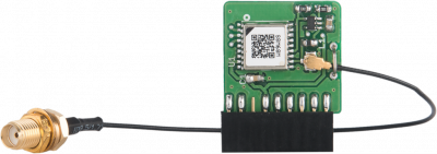
[[File:GPS.png|thumb|400px|GPS/Glonass expansion Module]] | |||
Module with GPS/Glonass module SIM68M. | |||
Model name: WBE-R-GPS | |||
Determination of coordinates. | Determination of coordinates. | ||
The time calibration signal. | The time calibration signal. | ||
== Antenna == | == Antenna == | ||
The module is not equipped with | The module is not equipped with the antenna. Antenna connection is made through u.FL. connector. | ||
When ordering the controller Wiren Board with the module, SMA type antenna connector installed on enclosure connector . | When ordering the controller Wiren Board with the module, SMA type antenna connector installed on enclosure connector. | ||
Power supply antenna: 3.3V. | Power supply antenna: 3.3V. | ||
== Data == | == Data == | ||
| Строка 23: | Строка 22: | ||
Data interchange with the module via the serial port. | Data interchange with the module via the serial port. | ||
Connection parameters: 9600 | Connection parameters: 9600 8N1. | ||
PPS signal is input to the "CS" extension slot. | PPS signal is input to the "CS" extension slot. | ||
== Operation in Wiren Board 5 == | == Operation in Wiren Board 5 == | ||
{| class="wikitable" | {| class="wikitable" | ||
! | !Extension module | ||
! | !Serial port | ||
!PPS GPIO | !PPS GPIO | ||
|- | |- | ||
| Строка 43: | Строка 41: | ||
|83 | |83 | ||
|} | |} | ||
== Module installation == | |||
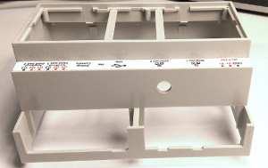
[[File:Drill_the__Hole.png|300px|thumb|left|SMA connector Hole]] | |||
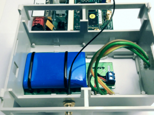
[[File:Battery_and_SMA.png|300px|thumb|right|Convenient location of the SMA connector and the WBMZ battery module ]] | |||
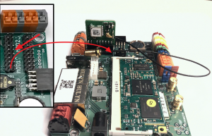
[[File:Insert_the_Module.png|300px|thumb|left|Insert the extension module, keeping the connector orientation]] | |||
[[File:Attach_the_Antenna.png|300px|thumb|right|Fix the SMA-socket and connect the antenna]] | |||
Appropriate instructions for disassembling the enclosure can be found [[Разбираем корпус контроллера/en| here]]. | |||
After the controller body is disassembled, proceed to the installation of the module and SMA-connector for connecting an external antenna. | |||
In the side wall of the upper part of the controller body, drill a hole with a diameter of ~6.5 mm. | |||
The location shown in the figure is the most convenient for mounting the connector: even if you have a WBMZ battery module installed, it will not prevent the connector from being attached. | |||
Install GPS/GLONASS module, as shown in the figure, observing the polarity. See also [[Модули_расширения/en|Extension modules]]. | |||
Fix module SMA-socket in the drilled hole in the case with nuts and connect the external antenna. | |||
When reassembling the case, make sure that the connecting cable from the module to the SMA socket does not get caught between the indicator and the plastic transparent light guide on the top cover of the Wiren Board controller. | |||
[[Получение_точного_времени_через_GPS/Glonass/en| NTPD configuration with NMEA and PPS]] | |||
Текущая версия на 14:50, 3 июля 2019
Module with GPS/Glonass module SIM68M. Model name: WBE-R-GPS
Determination of coordinates.
The time calibration signal.
Antenna
The module is not equipped with the antenna. Antenna connection is made through u.FL. connector.
When ordering the controller Wiren Board with the module, SMA type antenna connector installed on enclosure connector.
Power supply antenna: 3.3V.
Data
The data come from the module in the format NMEA. To work in Linux, you can use the software gpsd from our repository, or any other.
Data interchange with the module via the serial port.
Connection parameters: 9600 8N1.
PPS signal is input to the "CS" extension slot.
Operation in Wiren Board 5
| Extension module | Serial port | PPS GPIO |
|---|---|---|
| MOD1 | /dev/ttyAPP2 | 91 |
| MOD2 | /dev/ttyAPP3 | 83 |
Module installation
Appropriate instructions for disassembling the enclosure can be found here.
After the controller body is disassembled, proceed to the installation of the module and SMA-connector for connecting an external antenna.
In the side wall of the upper part of the controller body, drill a hole with a diameter of ~6.5 mm.
The location shown in the figure is the most convenient for mounting the connector: even if you have a WBMZ battery module installed, it will not prevent the connector from being attached.
Install GPS/GLONASS module, as shown in the figure, observing the polarity. See also Extension modules.
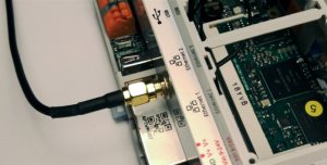
Fix module SMA-socket in the drilled hole in the case with nuts and connect the external antenna.
When reassembling the case, make sure that the connecting cable from the module to the SMA socket does not get caught between the indicator and the plastic transparent light guide on the top cover of the Wiren Board controller.
