Wiren Board Smart Home 3.5/en: различия между версиями
(Новая страница: «Wiren Board Smart Home 3.5») |
(Новая страница: «==External device connection examples== BMP085 and BMP180 sensors») |
||
| (не показана 21 промежуточная версия этого же участника) | |||
| Строка 1: | Строка 1: | ||
<languages/> | <languages/> | ||
'''Wiren Board Smart Home 3.5''' | '''Wiren Board Smart Home 3.5''' is an outdated version of the controller for automation. For a description of the current version, click [[Wiren Board 6 | here]]. | ||
== | == Description== | ||
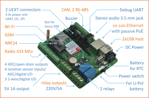
[[ | [[File:WB3.3 MAIN.png|thumb|500px|Wiren Board Smart Home rev 3.5 components]] | ||
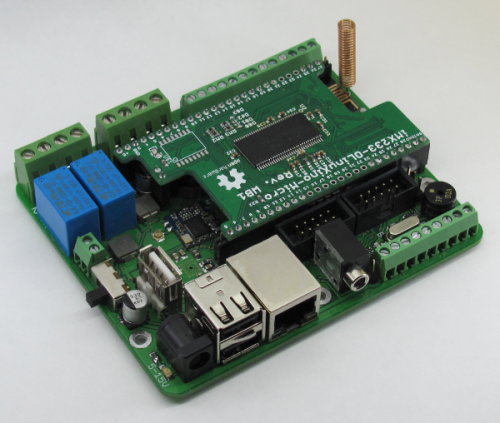
[[File:IMG 0260.png|thumb|500px|Wiren Board Smart Home rev. 3.5 top]] | [[File:IMG 0260.png|thumb|500px|Wiren Board Smart Home rev. 3.5 top]] | ||
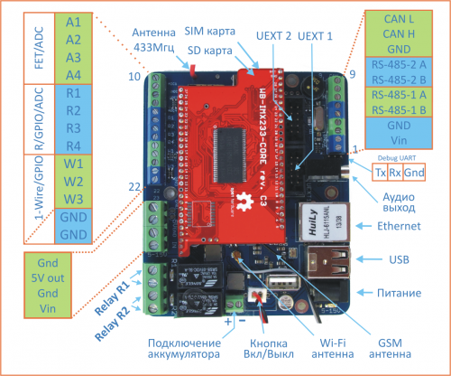
[[File:WB3.5.png|thumb|500px|Wiren Board Smart Home rev. 3.5 | [[File:WB3.5.png|thumb|500px|Wiren Board Smart Home rev. 3.5 designations]] | ||
Wiren Board Smart Home 3.5 | Wiren Board Smart Home 3.5 consists of two circuit boards: | ||
* | * modified [[iMX233-OLinuXino-micro/en]] - [[WB-IMX233-core/en]] | ||
* | * Main Board Wiren Board v. 3.5 | ||
Main Board contains: | |||
* [[Wi-Fi]] | * [[Wi-Fi/en]] based on Realtek chip [[rtl8188/en]] | ||
* GSM/GPRS | * GSM/GPRS networks and modem - Simcom [[SIM900R/en]] | ||
* USB to Ethernet | * USB to Ethernet USB USB hub, SMSC [[lan9514/en]] | ||
* [[RS-485]] - [http://www.analog.com/en/interface-isolation/rs-485-rs-422/adm3483/products/product.html ADM3483]. | * [[RS-485/en]] - [http://www.analog.com/en/interface-isolation/rs-485-rs-422/adm3483/products/product.html ADM3483]. | ||
* 8- | * 8-channel analog multiplexer for the ADC (4 terminal block АЦП1-ADC4 4 and the terminals P1-P4). See also [[ADC/en]]. | ||
* | * Outputs are "open collector" [[hardware_low_voltage_control/en|hardware low voltage load control]] | ||
* SPI-to-UART bridge IC | * SPI-to-UART bridge IC NXP [[SC16IS752/en]] | ||
* RTC | * RTC on-chip [[MCP79401/en]] (no devices installed by default, instead see [[SIM900R/en#RTC]]) | ||
* CAN | * CAN on chips [http://www.microchip.com/wwwproducts/devices.aspx?dDocName=en010406 MCP2515] and [http://www.microchip.com/wwwproducts/Devices.aspx?dDocName=en010405 MCP2551] | ||
* | * radio module [[rfm69h/en| rfm69h ]] 433MHz | ||
* | * radio module [[NRF24L01/en| NRF24L01]] 2.4 GHz | ||
* | * The power supply circuit on the chip LTC4002 | ||
== | ==Technical specifications== | ||
{| | {| border="1" class="wikitable" style="text-align:center" | ||
| | | || '''parameter''' || '''value'''|| '''Comments''' | ||
|- | |- | ||
|rowspan="3" | | |rowspan="3" | Software || Operating system || Debian Linux 7.0, mainline kernel 3.13 || | ||
|- | |- | ||
|rowspan="3" | | |rowspan="3" | Controller || CPU | 454mhz Freescale iMX233 || | ||
|- | |- | ||
|| | || RAM || 64 MB || | ||
|- | |- | ||
|| | || Non-volatile memory || +4Gb || SD card, can install flash memory chip | ||
|- | |- | ||
|rowspan="4" | | |rowspan="4" | Wireless || Wi-Fi || || | ||
|- | |- | ||
|| [[SIM900R|GSM/GPRS]] || | || [[SIM900R|GSM/GPRS]] || 1 SIM card || microSIM | ||
|- | |- | ||
|| NRF24 || 2 | || NRF24 || 2.4 GHz || for communication with the same NRF24 modules | ||
|- | |- | ||
|| | || packet radio || 433 MHz || management of the Noolite, chinese modules | ||
|- | |- | ||
|rowspan="9"| | |rowspan="9"| Ports | Ethernet || 10/100 (RJ-45)|| | ||
|- | |- | ||
|| USB 2.0 || | || USB 2.0 || 2 ports (+ one in) || | ||
|- | |- | ||
|| [[ | || [[Audio output]] ||1x || 3.5 mm Stereo Audio Jack | ||
|- | |- | ||
||[[RS-485]]|| 2x, | ||[[RS-485]]|| 2x, uninsulated ||<strike>DMX512 light Control</strike>, | ||
connection via MOD-bus, A-Bus | |||
|- | |- | ||
||[[RS-232]]|| | ||[[RS-232]]|| full-Duplex, non-isolated. || Connects parallel to the second RS-485 | ||
|- | |- | ||
|| [[Debug UART]]|| | || [[Debug UART]]|| debug console Output || Connects via UART-USB adapter. | ||
|- | |- | ||
||[[CAN | ||[[CAN bus]]|| 1x | | ||
|- | |- | ||
||[[1-Wire]] || 3x || | ||[[1-Wire]] || 3x || Connect 1-Wire temperature sensors, etc. | ||
|- | |- | ||
||[[UEXT]]|| 2x || | ||[[UEXT]]|| 2x || connection of extension modules from Olimex | ||
|- | |- | ||
|rowspan="3"| | |rowspan="3"| sensor Connection || [[ADC | ADC]] || 4 x - up to 30V (??), 4 x - up to 3.3 V || | ||
|- | |- | ||
||[[ | ||[[Inputs for resistive sensors]] || 4 x || include the thermistors 10 kω. | ||
|- | |- | ||
|| [[ | || [[Dry contact inputs]] | | 3 x || Connection of buttons, reed switches, counters with pulse outputs. | ||
|- | |- | ||
|rowspan="2"| | |rowspan="2"| Outputs || [[low voltage load Control]] || 4 outputs, 30V/2A || open collector Outputs", | ||
control of led strips, motors, etc. | |||
|- | |- | ||
|| [[WB_SH_3.5:_%D0%A1%D0%BF%D0%B8%D1%81%D0%BE%D0%BA_GPIO#GPIO_.D0.BD.D0.B0_.D1.80.D0.B5.D0.BB.D0.B5|Реле]]|| 2x 250V/2A || | | | [[WB_SH_3.5:_%D0%A1%D0%BF%D0%B8%D1%81%D0%BE%D0%BA_GPIO#GPIO_.D0.BD.D0.B0_.D1.80.D0.B5.D0.BB.D0.B5|Реле]]|| 2x 250V/2A || Normally open contacts. | ||
|- | |- | ||
|rowspan="3"| | |rowspan="3"| And || [[WB SH 3.5: GPIO List]] || 8x || multiplexed with other inputs/outputs | ||
|- | |- | ||
||[[Buzzer| | ||[[Buzzer|sound transducer]]|| 1x || "[[Buzzer/en|beeper]]". | ||
|- | |- | ||
|| | || Real time clock || RTC || Backup battery | ||
|- | |- | ||
|rowspan="2"| | |rowspan="2"| Power supply || Operating voltage || 5-15V ||rowspan="2"| Work from backup Li-Pol battery, | ||
power over Ethernet - PoE | |||
|- | |- | ||
|| | || Power consumption || <3 W | ||
|- | |- | ||
|rowspan="2"| | |rowspan="2"| Design || [[Wiren Board Drawing 3.3 | Dimensions]] || 103x87x20 mm | ||
|- | |- | ||
|| | || Housing || DIN rail ||D6MG by Gainta | ||
|- | |- | ||
|rowspan="1"| | |rowspan="1"|Operation || operating temperature || 0..70C (-40..85C on request) || | ||
|- | |- | ||
|} | |} | ||
== | == Terminals== | ||
{| | {| border="1" class="wikitable" style="text-align:center" | ||
| | | | ||
''' | '''signature''' | ||
||''' | ||'''Number''' | ||
''' | '''terminal plate''' | ||
|| ''' | || '''function'''|| '''Max. V, I"' || '''[[WB_SH_3.5:_Список_GPIO/en|GPIO]]''' || '''conclusion olinuxino''' || '''status''' | ||
''' | '''by default''' | ||
|| ''' | || '''comments''' | ||
|- | |- | ||
! colspan="8"| | ! colspan="8"| Top row, left block | ||
|- | |- | ||
| Vin || '''1''' | | Vin || '''1''' || Vin|| 15 || || || ||Input voltage; ADC channel 5 | ||
|- | |- | ||
| GND || '''2''' | | GND || '''2''' | | | GND | | | | | | | ||
|- | |- | ||
| RS-485-1 B || '''3''' | | RS-485-1 B|| '''3''' || [[RS-485]] B || +-6 V | | | | /dev/ttyNSC0 || 0V || | ||
|- | |- | ||
| RS-485-1 A || | | RS-485-1 A|| '''4''' || [[RS-485]] A || +-6 V || || /dev/ttyNSC0 || +3.3 V || | ||
|- | |- | ||
| RS-485-2 B || '''5''' | | RS-485-2 B|| '''5''' || [[RS-485]] B || +-6 V | | | | / dev/ttyNSC1 || 0V || | ||
|- | |- | ||
| RS-485-2 A || | | RS-485-2 A|| '''6''' || [[RS-485]] A || +-6 V || || /dev/ttyNSC1 || +3.3 V || | ||
|- | |- | ||
| GND || | | GND || '''7''' || GND | | | | | | | | ||
|- | |- | ||
| CAN H || '''8''' | | CAN H || '''8''' || CAN H ||+- 42V|||???? || || | ||
|- | |- | ||
| CAN L || '''9''' | | CAN L || '''9''' || CAN L ||+- 42V|||/??? || || | ||
|- | |- | ||
! colspan="8"| | ! colspan="8"| Bottom row, left block | ||
|- | |- | ||
| A1 || | | A1|| '''10''' || [[Управление низковольтной нагрузкой/en|FET]]/ADC1 || 30V, 2A|| 53 || 26 @ CON1 || High Z || open collector output, [[ADC/en]] channel 0 | ||
|- | |- | ||
| A2 || | | A2|| '''11''' || [[Управление низковольтной нагрузкой/en|FET]]/ADC2 || 30V, 2A|| 91 || 25 @ CON1 || High Z || open collector Output, [[ADC/en]] channel 1 | ||
|- | |- | ||
| A3 || | | A3|| '''12''' || [[Управление низковольтной нагрузкой/en|FET]]/ADC3] || 30V, 2A|| 56 || 22 @ CON1 || High Z || open collector Output, [[ADC/en]] channel 2 | ||
|- | |- | ||
| A4 || | | A4|| '''13''' || [[Управление низковольтной нагрузкой/en|FET]]/ADC4 || 30V, 2A|| 55 || 21 @ CON1 || High Z || open collector Output, [[ADC/en]] channel 3 | ||
|- | |- | ||
| R1 || | | R1 || '''14''' || R1/GPIO/ADC5 || 5V|| 16 || 19 @ CON1 || High Z || Resistive sensors, [[ADC/en]] channel 4 | ||
|- | |- | ||
| R2 || | | R2 || '''15'''| | R2/GPIO/ADC6 || 5V|| 7 || 18 @ CON1 || High Z || Resistive sensors, [[ADC/en]] channel 5 | ||
|- | |- | ||
| R3 || | | R3 || '''16'''|| R3/GPIO/ADC7 || 5V|| 6 || 17 @ CON1 || High Z || Resistive sensors, [[ADC/en]] channel 6 | ||
|- | |- | ||
| R4 || | | R4 || '''17'''| | R4/GPIO/ADC8 || 5V|| 5 || 16 @ CON1 || High Z || Resistive sensors, [[ADC/en]] channel 7 | ||
|- | |- | ||
| W1 || | | W1 || '''18''' || W1/GPIO || 3.3 V|| 4 || 15 @ CON1 || 3.3 V || 1-Wire,"dry contact" | ||
|- | |- | ||
| W2 || | | W2 || '''19''' || W2/GPIO || 3.3 V|| 2 || 13 @ CON1 || 3.3 V || 1-Wire,"dry contact" | ||
|- | |- | ||
| W3 || | | W3 || '''20''' || W3/GPIO || 3.3 V|| 1 || 12 @ CON1 || 3.3 V || 1-Wire,"dry contact" | ||
|- | |- | ||
| GND || | | GND || '''21''' || GND|| || || || || | ||
|- | |- | ||
| GND || | | GND || '''22''' || GND|| || || || || | ||
|- | |- | ||
! colspan="8"| | ! colspan="8"| Bottom row, right block | ||
|- | |- | ||
| GND || | | GND || '''23''' || GND|| || || || || | ||
|- | |- | ||
| 5V out || | | 5V out || '''24'''|| 5Vout|| 5V, 0.5 A | | | | | | | 5V output | ||
|- | |- | ||
| GND || '''25''' | | GND || '''25''' || GND | | | | | | | | ||
|- | |- | ||
| Vin || '''26''' | | Vin || '''26''' | | Vin || 15V || || || ||Input voltage; ADC channel 5 | ||
|- | |- | ||
| Relay 1 || | | Relay 1 || '''27-28''' || R1 || 250, 5A||247 || || open ||first relay | ||
|- | |- | ||
| Relay 2 || '''29-30''' | | Relay 2 || '''29-30''' || R2 || 250, 5A|| 246|| || open ||second relay | ||
|- | |- | ||
|} | |} | ||
== | == Power Supply== | ||
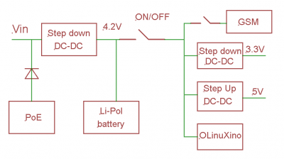
[[ | [[File:Питание 2.PNG|thumb|400px|WB 3.5 Power supply circuit]] | ||
''' | '''From external power supply''' | ||
===Power supply=== | |||
Supply voltage is 4.7-15V. | |||
The average consumption of the board is 1.5-2 watts. But since the GPRS module consumes up to 8W impulsively, it is recommended to use power supplies with a power of at least 10W. | |||
5.5x2.1mm power connector, also input voltage can be connected to terminals 1 and 26. | |||
'''Power over Ethernet''' | '''Power over Ethernet''' | ||
Power over Ethernet cable is supported, [http://ru.wikipedia.org/wiki/Power_over_Ethernet#Passive_PoE Passive PoE] voltage from 7 to 16 Volts. | |||
Power is transmitted in unused pairs: "+" ("-") pair 4-5 (blue, white and blue), "-" ("+") on paired 7-8 (brown, white-brown). Polarity doesn't matter. | |||
''' | '''Connecting PoE with the power supply causes damage to the power supply.''' | ||
See [[Power over Ethernet/en]]. | |||
''' | '''Battery''' | ||
Wiren Board | ===Battery=== | ||
The Wiren Board allows you to connect a Li-Ion (Li-Pol) battery with a maximum voltage of 4.2 V. When you connect the power, the battery is charged with a current of up to 0.5 A (depending on the load). | |||
There is protection against over-discharge of the battery, at a voltage below 2.9 V the battery is disconnected. However, it is recommended to use protected batteries. | |||
Also, there is no protection from charging at low temperatures. Be careful, the batteries deteriorate from this. | |||
''' | '''It is necessary to meet the battery polarity!''' | ||
== | == List of GPIOs == | ||
See [[WB_SH_3.5:_Список_GPIO/en]] | |||
===Debug UART=== | ===Debug UART=== | ||
Debug UART | Debug UART is output on the UEXT1 connector, and also separately on the comb (near the audio Jack, see diagram) | ||
Pins 2,3,4 are used for Debug UART (see picture). | |||
== | == Device drawings and pictures == | ||
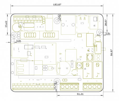
[[Файл:ЧертежWB3.3.png |thumb|500px|]] | [[Файл:ЧертежWB3.3.png |thumb|500px|]] | ||
''' | '''Schematic diagram of Wiren Board 3.5''' - [[Файл:СхемаWB3.5.pdf]] | ||
[[Файл:ЧертежWB3.3.pdf]] | [[Файл:ЧертежWB3.3.pdf]] | ||
== | ==External device connection examples== | ||
[[BMP085| | [[BMP085/en| BMP085 and BMP180 sensors]] | ||
Текущая версия на 19:21, 1 августа 2019
Wiren Board Smart Home 3.5 is an outdated version of the controller for automation. For a description of the current version, click here.
Description
Wiren Board Smart Home 3.5 consists of two circuit boards:
- modified iMX233-OLinuXino-micro/en - WB-IMX233-core/en
- Main Board Wiren Board v. 3.5
Main Board contains:
- Wi-Fi/en based on Realtek chip rtl8188/en
- GSM/GPRS networks and modem - Simcom SIM900R/en
- USB to Ethernet USB USB hub, SMSC lan9514/en
- RS-485/en - ADM3483.
- 8-channel analog multiplexer for the ADC (4 terminal block АЦП1-ADC4 4 and the terminals P1-P4). See also ADC/en.
- Outputs are "open collector" hardware low voltage load control
- SPI-to-UART bridge IC NXP SC16IS752/en
- RTC on-chip MCP79401/en (no devices installed by default, instead see SIM900R/en#RTC)
- CAN on chips MCP2515 and MCP2551
- radio module rfm69h 433MHz
- radio module NRF24L01 2.4 GHz
- The power supply circuit on the chip LTC4002
Technical specifications
| parameter | value | Comments | |
| Software | Operating system | Debian Linux 7.0, mainline kernel 3.13 | |
| Controller | 454mhz Freescale iMX233 | ||
| RAM | 64 MB | ||
| Non-volatile memory | +4Gb | SD card, can install flash memory chip | |
| Wireless | Wi-Fi | ||
| GSM/GPRS | 1 SIM card | microSIM | |
| NRF24 | 2.4 GHz | for communication with the same NRF24 modules | |
| packet radio | 433 MHz | management of the Noolite, chinese modules | |
| Ports | Ethernet | 10/100 (RJ-45) | ||
| USB 2.0 | 2 ports (+ one in) | ||
| Audio output | 1x | 3.5 mm Stereo Audio Jack | |
| RS-485 | 2x, uninsulated | connection via MOD-bus, A-Bus | |
| RS-232 | full-Duplex, non-isolated. | Connects parallel to the second RS-485 | |
| Debug UART | debug console Output | Connects via UART-USB adapter. | |
| CAN bus | |||
| 1-Wire | 3x | Connect 1-Wire temperature sensors, etc. | |
| UEXT | 2x | connection of extension modules from Olimex | |
| sensor Connection | ADC | 4 x - up to 30V (??), 4 x - up to 3.3 V | |
| Inputs for resistive sensors | 4 x | include the thermistors 10 kω. | |
| Dry contact inputs | | 3 x | Connection of buttons, reed switches, counters with pulse outputs. | ||
| Outputs | low voltage load Control | 4 outputs, 30V/2A | open collector Outputs",
control of led strips, motors, etc. |
| Реле | 2x 250V/2A | Normally open contacts. | |
| And | WB SH 3.5: GPIO List | 8x | multiplexed with other inputs/outputs |
| sound transducer | 1x | "beeper". | |
| Real time clock | RTC | Backup battery | |
| Power supply | Operating voltage | 5-15V | Work from backup Li-Pol battery,
power over Ethernet - PoE |
| Power consumption | <3 W | ||
| Design | Dimensions | 103x87x20 mm | |
| Housing | DIN rail | D6MG by Gainta | |
| Operation | operating temperature | 0..70C (-40..85C on request) |
Terminals
|
signature |
Number
terminal plate |
function | Max. V, I"' | GPIO | conclusion olinuxino | status
by default |
comments |
| Top row, left block | |||||||
|---|---|---|---|---|---|---|---|
| Vin | 1 | Vin | 15 | Input voltage; ADC channel 5 | |||
| GND | | | GND | | | | | | | ||||||
| RS-485-1 B | 3 | RS-485 B | | | | /dev/ttyNSC0 | 0V | |||
| RS-485-1 A | 4 | RS-485 A | +-6 V | /dev/ttyNSC0 | +3.3 V | ||
| RS-485-2 B | 5 | RS-485 B | | | | / dev/ttyNSC1 | 0V | |||
| RS-485-2 A | 6 | RS-485 A | +-6 V | /dev/ttyNSC1 | +3.3 V | ||
| GND | 7 | | | | | | | | |||||
| CAN H | 8 | CAN H | +- 42V | ???? | |||
| CAN L | 9 | CAN L | +- 42V | /??? | |||
| Bottom row, left block | |||||||
| A1 | 10 | FET/ADC1 | 30V, 2A | 53 | 26 @ CON1 | High Z | open collector output, ADC/en channel 0 |
| A2 | 11 | FET/ADC2 | 30V, 2A | 91 | 25 @ CON1 | High Z | open collector Output, ADC/en channel 1 |
| A3 | 12 | FET/ADC3] | 30V, 2A | 56 | 22 @ CON1 | High Z | open collector Output, ADC/en channel 2 |
| A4 | 13 | FET/ADC4 | 30V, 2A | 55 | 21 @ CON1 | High Z | open collector Output, ADC/en channel 3 |
| R1 | 14 | R1/GPIO/ADC5 | 5V | 16 | 19 @ CON1 | High Z | Resistive sensors, ADC/en channel 4 |
| R2 | | R2/GPIO/ADC6 | 5V | 7 | 18 @ CON1 | High Z | Resistive sensors, ADC/en channel 5 | |
| R3 | 16 | R3/GPIO/ADC7 | 5V | 6 | 17 @ CON1 | High Z | Resistive sensors, ADC/en channel 6 |
| R4 | | R4/GPIO/ADC8 | 5V | 5 | 16 @ CON1 | High Z | Resistive sensors, ADC/en channel 7 | |
| W1 | 18 | W1/GPIO | 3.3 V | 4 | 15 @ CON1 | 3.3 V | 1-Wire,"dry contact" |
| W2 | 19 | W2/GPIO | 3.3 V | 2 | 13 @ CON1 | 3.3 V | 1-Wire,"dry contact" |
| W3 | 20 | W3/GPIO | 3.3 V | 1 | 12 @ CON1 | 3.3 V | 1-Wire,"dry contact" |
| GND | 21 | GND | |||||
| GND | 22 | GND | |||||
| Bottom row, right block | |||||||
| GND | 23 | GND | |||||
| 5V out | 24 | 5Vout | | | | | | | 5V output | ||||
| GND | 25 | | | | | | | | |||||
| Vin | | Vin | 15V | Input voltage; ADC channel 5 | ||||
| Relay 1 | 27-28 | R1 | 250, 5A | 247 | open | first relay | |
| Relay 2 | 29-30 | R2 | 250, 5A | 246 | open | second relay | |
Power Supply
From external power supply
Power supply
Supply voltage is 4.7-15V. The average consumption of the board is 1.5-2 watts. But since the GPRS module consumes up to 8W impulsively, it is recommended to use power supplies with a power of at least 10W.
5.5x2.1mm power connector, also input voltage can be connected to terminals 1 and 26.
Power over Ethernet
Power over Ethernet cable is supported, Passive PoE voltage from 7 to 16 Volts. Power is transmitted in unused pairs: "+" ("-") pair 4-5 (blue, white and blue), "-" ("+") on paired 7-8 (brown, white-brown). Polarity doesn't matter. Connecting PoE with the power supply causes damage to the power supply.
Battery
Battery
The Wiren Board allows you to connect a Li-Ion (Li-Pol) battery with a maximum voltage of 4.2 V. When you connect the power, the battery is charged with a current of up to 0.5 A (depending on the load). There is protection against over-discharge of the battery, at a voltage below 2.9 V the battery is disconnected. However, it is recommended to use protected batteries.
Also, there is no protection from charging at low temperatures. Be careful, the batteries deteriorate from this.
It is necessary to meet the battery polarity!
List of GPIOs
Debug UART
Debug UART is output on the UEXT1 connector, and also separately on the comb (near the audio Jack, see diagram)
Pins 2,3,4 are used for Debug UART (see picture).
Device drawings and pictures
Schematic diagram of Wiren Board 3.5 - Файл:СхемаWB3.5.pdf
