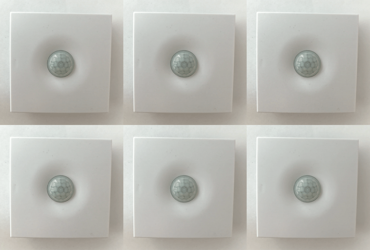
Wall-mounted 8-in-one sensor WB-MSW v.3
Buy online Внимание: Отображаемое название «Wall-mounted 8-in-one sensor WB-MSW v.3» переопределяет ранее заданное отображаемое название «WB-MSW v.3».
Purpose
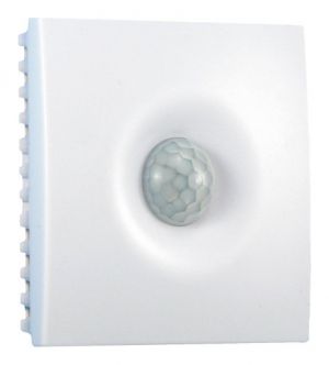
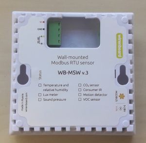
WB-MSW v.3 module combines digital sensors of temperature, humidity, illumination, sound pressure, the concentration of VOC, Volatile organic compounds, motion sensor and transmission of IR commands. When ordering, you can select a combination of sensors to be installed in the module. Designed for domestic use. Design: plastic housing, wall-mounted. The module is controlled from the controller or PC via RS-485 bus by Modbus RTU Protocol commands.
| The article about the sensor of the previous generation WB-MSW is here: WB-MSW2 Sensor. |
|---|
Specifications
| Measured value | Range | Error | Ready
after power-on |
|---|---|---|---|
| Concentration CO2 | 0 — 5000 ppm (ppm) | 50 ppm | 3 min
(self-calibration after 24h) |
| Temperature | -40°C — +80°C | ±0.3°C (range 0°C — 70°C)
±0.5°C (full range) |
1 sec |
| Relative humidity | 0 — 99.9% (operating range: 0 — 98%) | ±3% | 1 sec |
| Noise level (sound pressure) | 40 — 82 dB | ±3 dB | 5 sec |
| Illumination | 0,02 — 100 000 Lux | ±10% | 1 sec |
| Air quality
(Volatile organic compounds) |
0 ppm - 60000 ppb (billion shares) by ethanol | ±15%(type)
±40%(max) |
5 min.
(self-calibration after 12h) |
| Motion sensor | up to 8 m, 120 degree | 5 sec | |
| Transmitting IR commands | up to 10 m (depends on ambient conditions) |
| Option | Value | ||
|---|---|---|---|
| Power | |||
| Supply voltage | 9 V — 28 V DC | ||
| Power consumption |
0.5 W | ||
| Number of stored IR commands | |||
| Number of commands |
32 | ||
| Command duration | The maximum command length is 508 registers, plus two registers indicate the end of the command.
Each register encodes the duration of a high or low signal level (sequentially) in microseconds. | ||
| Terminals and wire section | |||
| The recommended wire cross section with pin bushing insulated tip, mm2 | 0,75 — 1 | ||
| Standard sleeve length of pin bushing insulated tip, mm | 8 | ||
| Tightening torque of screws, Н∙м | 0,2 | ||
| Control | |||
| Management interface | RS-485 | ||
| Interface isolation | Uninsulated | ||
| Communication protocol | Modbus RTU, the address is set by software, factory settings are indicated on the label | ||
| RS-485 interface parameters |
speed 9600 bps; data bits 8; parity N; stop bits 2; The interfaces can be configured programmatically:
| ||
| Display | |||
| Power and data exchange | green led at the bottom of the case | ||
| Custom indicator | green and red led with adjustable flashing frequency and duty cycle | ||
| Sound indication | beeper | dimensions | |
| Size | 83x90,83x20 mm | ||
| Operating conditions | |||
| Air temperature | -40°C to +80°C | ||
| Relative humidity | up to 98%, no condensation | ||
Modifications
Characteristics are coded in the article, according to the following scheme:
| Designation | Supported function |
|---|---|
| TH | temperature and humidity measurement |
| L | light measurement |
| I | IR transceiver |
| S | sound pressure level measurement |
| M | motion sensor |
| C | CO2 concentration measurement |
| V | VOC concentration measurement |
Data exchange
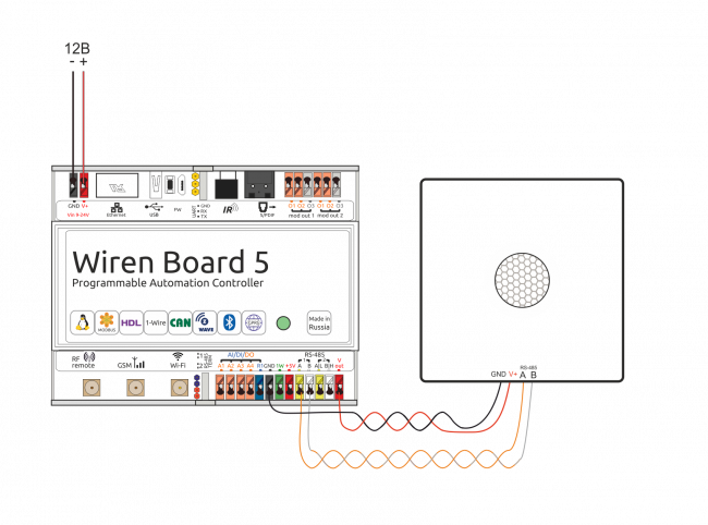
At the physical level, the module is connected via RS-485 interface. Modbus RTU Protocol is used to control the WB-MSW sensor. In Wirenboard Devices, Modbus data is transmitted over RS-485 communication lines. See the Modbus Protocol page for details. Modbus-the address of the counter is set at the factory and marked on the label. The address can be changed programmatically. Details refer to the Modbus control.
Installation
The module has holes for mounting to the surface. The installation pattern for body sensor: Файл:Установочный шаблон WB-MSW3 .pdf. To print a template, save it, open it in Acrobat Reader and select the "Real scale" option when printing.
For mounting the module, choose screws/screws with a head diameter of about 7 mm, if you want the module to be removable, and 9-10 mm — for permanent fixation.
The screw terminal block of the module is located on its back side and is used to connect power lines (V+ and GND) and control over RS-485 (RS-485 A and B). When using type handpieces for installation of wires in screw clamps, it is necessary that the diameter of the insulated cuffs does not exceed 3.6 mm, the wire section — 0.75 mm2, and the length of the conductive sleeve — 6 mm. Screw clamps also accept wire section up to 1.5 mm2.
Module connection to RS-485 process is described RS-485:Физическое_подключение/en / here in detail.
The module must be operated under recommended environmental conditions.
The recommended mounting height of the sensor from the floor level is 1 — 1.6 m.
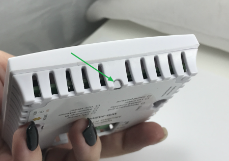
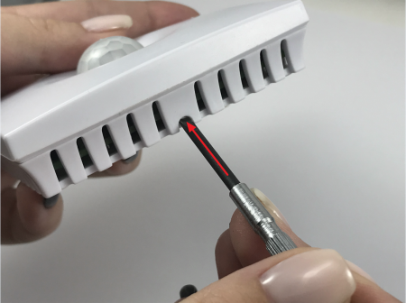
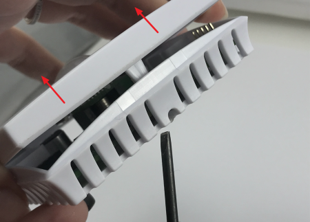
How to open the sensor housing
| Locate the latch tab on the underside of the sensor housing. | Push the screwdriver against the tab perpendicular to the side of the sensor housing until it stops. | Lift the top cover of the sensor. |
Th and VOC modules
Temperature/humidity (TH) and VOC measurement are done on separate modules. Modules are installed on the arrow in the connectors. For more accurate measurement, the TH module must be installed in the upper left connector. Otherwise it is heated by the CO2 sensor and overestimates the reading by 1-2 degrees.
Indication
The module has an indicator of operation and data exchange, which is visible in the technological hole on the bottom of the case. This indicator is not visible when the module is mounted on the wall, but is convenient when connecting and configuring the device. For the main indication in the module, there are two LEDs, green and red, which illuminate the lens on the front surface of the module (see below). The module has a sound beeper to attract attention. The beeper is also controlled via Web-interface or Modbus-register. For more information, see Modbus Control.
Motion sensor
The module has a PIR motion sensor that detects the movement of objects at a distance of up to 8 m with a viewing angle of about 100 degrees. The module has 3 Modbus-registers related to the data received from the sensor, and one register that specifies the window time to calculate the maximum traffic intensity for the past time interval.
The operation principleof the motion detection mechanism in the WB-MSW v.3 sensor is as follows. The module constantly receives "raw" values from the ADC to which the motion sensor is connected (register 281). In the absence of movement, these values are virtually unchanged. When moving radiating in the IR range of the object in the field of view of the sensor is a sharp increase and a sharp decline in the values read from the ADC. Changes in raw values immediately increase the value of Current motion (the current average of the intensity of movement), which then begins to slowly subside for a few seconds. Each new sharp change in the value received from the ADC, again "charges" the register Current motion. Max Motion in the register is recorded on the maximum value of the Current register of motion in the last N seconds (N is the width of the time window over which is calculated the maximum value recorded in the storage register 282).
The device template contains two parameters: Current motion and Max Motion. If the motion sensor is polled quickly (several times per second), we can use the Current motion parameter to detect motion with good time resolution. If the sensor is rarely polled (for example, every 30 seconds, in a large network), then we can skip the rapid single movement of the object: in this case, we should use the value Max Motion and set the width of the time window for calculating the maximum number of motion is obviously greater than the sensor polling period.
The intensity value of the movement allows you to programmatically in the rules engine to react in different ways at different thresholds.
LED lights
The module has two bright LEDs, green and red, illuminating the lens on the front surface of the module. The switching on, frequency and duration of led flashes are set in the web interface or in the corresponding Modbus registers. The periodicity and duration are the same for both LEDs, so when they are switched on simultaneously, they will flash synchronously. Constant glow mode is not provided.
Indicators provide feedback during installation and operation. For example, the sensor may blink red when the optimum carbon dioxide concentration is exceeded. When mounting a large number of sensors, indicators or beeper will help you determine which sensor you are currently accessing.
IR remote emulation
In WB-MSW v.3 the IR receiver for learning and 8 IR LEDs are under the lens.
Detailed description and use of the module, and a map of the registers is described in section how to work with the IR receiver in the WB-MS WB-MSW, WB-MIR devices.
The training is done once — the commands are stored in the device memory and can be played back by the Modbus command from the controller. The number of stored commands is large enough (up to a hundred, depending on the model of the console) to control many devices in the room at once. The power of the transmitter is enough for the controlled devices to receive not only a direct but also a reflected signal.
In non-residential premises, the IR provides control of air conditioning and heating plants. Note that IR commands are sent to all devices in sight, so you will not be able to send different commands to the same devices. For individual control of each air conditioner use the module WB-MIR.
Light sensor
The light sensor of the module has a filter that repeats the spectral sensitivity curve of the human eye. This allows you to measure the illumination in the suites, which allows you to control the illumination, in accordance with the norms of SanPiN.
LED indicators, light sensor and IR LEDs are made on one separate module, depending on the configuration when buying them may not be.
Noise sensor
The module uses a microphone with an amplifier and filters for correction on a scale, taking into account the peculiarities of the human ear perception of sounds of different frequencies. Noise is measured in acoustic decibels (dBA), which allows you to control the noise environment in accordance with standards and sanitary norms.
VOC sernsor
Volatile organic compounds constitute the volatile substances released in the atmosphere as gases. The sensor determines the total concentration of volatile organic substances, including the evaporation of varnishes/paints and interior decoration elements (phenol, formaldehyde, toluene, styrene), alcohols, benzene, rotting vegetables, human gases, household gas. High concentrations of dangerous VOC pose a threat to human life and health. The VOC sensor does not work as a household combustible gas leak detector!
The sensor measures the total concentration of volatile organic substances in units per billion ppb (also called OLOS — see GOST R ISO 16000-9-2009). This parameter characterizes the total concentration of VOC in the average room. Based on the studies by the manufacturer of the sensor has established the following thresholds of concentration:
| Concentration (ppb) | Level | Compliance with hygienic standards | Recommendations | Exposure time limit |
|---|---|---|---|---|
| 2200 - 5500 | Dangerous to health | serious | to be affected only in cases of emergency / Need intensive ventilation | watch |
| 660-2200 | Unsatisfactory | big beef | Required intensive ventilation or ventilation is required in the search of sources of pollution | < 1 month |
| 220 - 660 | Acceptable | Some claims | intensive ventilation or airing is Recommended, search for sources of pollution is required | < 12 months |
| 65 - 220 | Good | No special complaints | Recommended ventilation or ventilation | no limit |
| 0-65 | Excellent | No claims | Required value | no limit |
The sensor is ready for operation 6 minutes after switching on. Prior to this, the air quality register contains an error value (0xFFFF). Approximately every 12 hours, there is a self-calibration of the sensor.
Warning: the sensor does not respond to smoke!
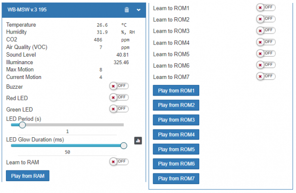
Representation of WB-MSW v.3 in the Wiren Board web interface
The table lists the names of the parameters measured by the module and their values. The names of parameters that are not supported by a particular module will be highlighted in red.
| Parameter | Value |
|---|---|
| Temperature | Internal sensor temperature |
| Humidity | Relative humidity percentage |
| Air Quality (VOC) | Air quality (FISHING) in ppm |
| CO2 | Co2 concentration in PPM |
| Sound Level | Sound pressure in dB |
| Illumination | Illumination in Lux |
| Max Motion | Maximum averaged value of the motion sensor for the last N seconds (N — adjustable parameter, register 282) |
| Current Motion | The average value of the motion sensor for a short interval of time |
| Buzzer | Enable(ON)/disable(OFF) beep sound |
| Red LED | On/off flashing red led |
| Green LED | On/off flashing red led |
LED Period (s)
The period between flashes of the LEDs in seconds | |
| LED Glow Duration (ms) | Duration of led flashes in milliseconds |
| Learn to RAM — Reset all ROM | IR control transmitter, see control via IR |
| Input Voltage | Input voltage in volts |
| Serial | Device serial number |
Additional functions
Address change is broadcast (slave_id 0) team record (WRITE_SINGLE_REGISTER) to holding register with address 128 (0x80).
Device firmware update
Starting with the new firmware versions of the device, the firmware update functionality (firmware) via the Modbus Protocol is supported. This makes it possible to extend the functionality of the devices and eliminate errors in the firmware directly at the installation site.
Read more about flashing devices described in the article Download firmware to Wiren Board devices.
A list of firmware versions that support the update, as well as devices for which this feature is implemented, can be found in Firmware_Changelog .
Modbus Control
Details of the work with the module via Modbus Protocol is written in Relay Modules Modbus Management . There you can also find a map of the device registers.
Back to peripheral devices list
Images and drawings of the device
По ссылкам ниже вы можете скачать изображения и чертежи устройства WB-MSW3.
Corel Draw 2018: WB-MSW3.cdr.zip
Corel Draw PDF: WB-MSW3.cdr.pdf
Autocad 2013 DXF: WB-MSW3.dxf.zip
Autocad PDF: WB-MSW3.pdf
