WB-MIO Modbus Interface Converters/en: различия между версиями
(Новая страница: «==Connection of I/O modules==») |
(Новая страница: «I/O modules are connected to the WB-MIO by connecting to it from the side (entering the side connector). File:Connecting_Side_Modules.png|250px|thumb|right| Con…») |
||
| Строка 154: | Строка 154: | ||
==Connection of I/O modules== | ==Connection of I/O modules== | ||
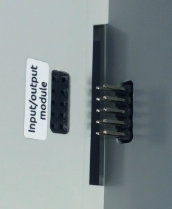
I/O modules are connected to the WB-MIO by connecting to it from the side (entering the side connector). | |||
[[ | [[File:Connecting_Side_Modules.png|250px|thumb|right| Connecting the module to WB-MIO]] | ||
Версия 16:34, 19 июля 2019
Buy WB-MIO in the online store Buy WB-MIO-E online store
Purpose
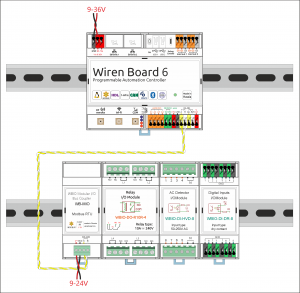
WB-MIO and WB-MIO-E interface converters are designed for remote connection of devices "WBIO" (I/O modules) via Modbus RS-485 or Ethernet (in WB-MIO-E). Allow, if necessary, to separate the I/O modules from the Wiren Board controller and transfer to another DIN rail or to another shield. It also allows you to use I/O modules as a separate device with controllers from other manufacturers.
Interface conversion
There are three modifications of WB interface converters: WB-MIO, WB-MIO-E and WB-MGE. The table below shows which interface each module converts to.
| Model | From | To | |||
|---|---|---|---|---|---|
| RS-485
(Modbus) |
Ethernet
(IP) |
WBIO | RS-485
(Modbus) |
Ethernet
(IP) | |
| WB-MIO | + | + | |||
| WB-MIO-E | + | + | + | ||
| WB-MGE | + | + | + | + | |
Technical specifications
| Option | Value |
|---|---|
| Power | |
| Supply voltage front-end | 9 V — 24 V DC |
| Power consumption |
0.85 W |
| Terminals and wire section | |
| Recommended wire cross-section, mm2 | 0,75 — 1 |
| Length of the standard sleeve, mm | 8 |
| Torque of screws, N∙m | 0,2 |
| Communication | |
| Communication protocol | Modbus RTU, WBIO |
| Interfaces |
|
| RS-485 interface parameters | set programmatically, by default:
speed 9600 bps; data bits 8; parity N; stop bits 2;
|
| dimensions | |
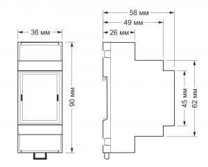
| Size | 2 DIN; 36,3x90,2x57,5 mm |
| Operating conditions | |
| Air temperature | -40°C to +80°C |
| Relative humidity | up to 92%, no condensation |
Modifications
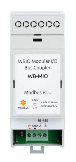
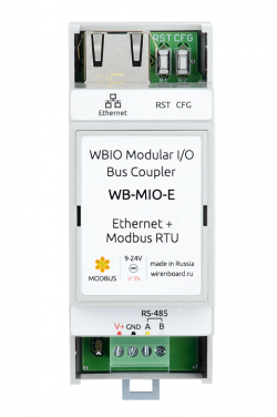
Interface module WB-MIO is available in two versions, characterized by the presence of Ethernet interface: WB-MIO and WB-MIO-E.
| Modification | RS-485 interface | Ethernet interface |
|---|---|---|
| WB-MIO | yes | no |
| WB-MIO-E | yes | yes |
RS-485 interface connection
WB-MIO(-E) is connected to the controller via connectors A and B RS-485. If power is supplied from a separate power supply, the ground of the controller and the power supply must be combined.
See article RS-485:Physical connection.
The WB-MIO module is a peripheral device (slave) in the Modbus network.
Ethernet connection
Modification WB-MIO-E with Ethernet interface is connected to the local Ethernet network: to the router port or directly to one of the Ethernet ports of the programmable Wiren Board controller.
WB-MIO-E power is supplied to V+ and GND terminals. Module WB-MIO-E does NOT support PoE.
On the default Ethernet network, WB-MIO-E' has a static IP address of 192.168.0.7. To work with the Wiren Board controller software, the Ethernet part of the WB-MIO-E module must be configured in "TCP Server" mode. Detailed instructions on how to configure the Ethernet part of WB-MIO-E can be found on configuring Ethenet interfaces and connecting WB-MIO-E and WB-MGE modules].
Connection of I/O modules
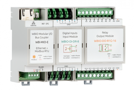
I/O modules are connected to the WB-MIO by connecting to it from the side (entering the side connector).
Последовательно можно подключать до 9 модулей: до 4 модулей ввода (типа "I"), до 4-х модуля вывода и ввода-вывода (тип "O" и "IO"), один модуль WBIO-AI-DV-12. Тип модуля определяет тип адресации модуля контроллером на шине бокового разъема. Адреса раздаются последовательно. Подключать до 4 модулей можно в любой последовательности. При большем числе следует подключать сначала один тип, потом другой.
Настройка в web-интерфейсе
За работу с WB-MIO(-E), подключёнными по RS-485 или Ethernet, в Wiren Board отвечает Драйвер wb-mqtt-serial.
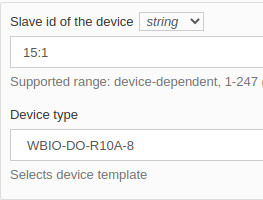
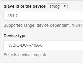
Для подключения WBIO (Модулей ввода-вывода) через WB-MIO необходимо зайти в web-интерфейс контроллера, перейти в меню во вкладку Configs, выбрать файл /etc/wb-mqtt-serial.conf. Далее нужно добавить к нужному порту новый Serial device. В поле "Slave id of the device" указываем адрес устройства WB-MIO и через двоеточие номер по счету подключенного к нему модулю ввода-вывода.
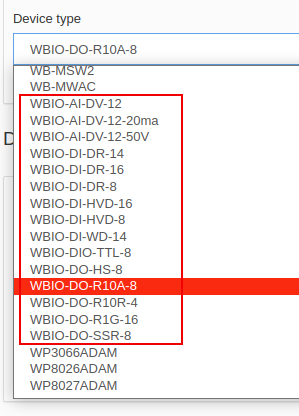
Например, если у нас к WB-MIO подключен всего один модуль, то строка "Slave id of the device" для этого модуля будет выглядеть так: 15:1. Где 15 - это Modbus-адрес WB-MIO, а 1 это номер по счету модуля ввода-вывода. В поле "Device type" необходимо выбрать тип подключенного модуля. Названия шаблонов для них начинаются на "WBIO-..."
Управление по Modbus
Карту Modbus-регистров WB-MIO и WB-MIO-E можно найти на странице WB-MIO-Modbus-Registers. Дополнительную информацию о работе с устройствами по протоколу Modbus можно найти в разделе Протокол Modbus
Изображения и чертежи устройства
По ссылкам ниже вы можете скачать изображения и чертежи устройства WB-MIO.
Corel Draw 2018: WB-MIO.cdr.zip
Corel Draw PDF: WB-MIO.cdr.pdf
Autocad 2013 DXF: Мы еще не подготовили чертеж этого устройства. Вы можете запросить чертеж устройства "Bus coupler WB-MIO" на портале техподдержки Wiren Board (необходима регистрация).
По ссылкам ниже вы можете скачать изображения и чертежи устройства WB-MIO-E.
Corel Draw 2018: WB-MIO-E.cdr.zip
Corel Draw PDF: WB-MIO-E.cdr.pdf
Autocad 2013 DXF: WB-MIO-E.dxf.zip
Autocad PDF: WB-MIO-E.pdf
