Wiren Board NETMON-2/en: различия между версиями
(Новая страница: «Wiren Board NETMON-2») |
(Новая страница: «See Supported devices») |
||
| (не показано 47 промежуточных версий этого же участника) | |||
| Строка 1: | Строка 1: | ||
<languages/> | <languages/> | ||
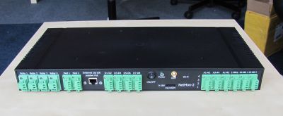
Wiren Board NETMON-2 - | Wiren Board NETMON-2 is a universal controller for automation with open software based on Linux, a built-in GSM modem and designed in a case for installation in a 19" rack. | ||
Designed for monitoring of network and telecommunication equipment, polling of sensors and counters, remote power management. | |||
| Строка 11: | Строка 11: | ||
[[Файл:Netmon2 front photo.jpg|thumb|400px|Wiren Board NETMON-2]] | [[Файл:Netmon2 front photo.jpg|thumb|400px|Wiren Board NETMON-2]] | ||
== | ==Technical specifications== | ||
The controller is identical in hardware to the set of: | |||
1. [[Wiren Board 5]] | 1. [[Wiren Board 5/en| Wiren Board 5]] | ||
2. [[Модуль релейных выходов 10A (WBIO-DO-R10A-8)| | 2. [[Модуль релейных выходов 10A (WBIO-DO-R10A-8)/en|WBIO-DO-R10A-4]]- 4 SPST 10A/230V relays | ||
3. [[Модуль дискретных входов типа "сухой контакт" (WBIO-DI-DR-8)]] | 3. [[Модуль дискретных входов типа "сухой контакт" (WBIO-DI-DR-8)/en| WBIO-DI-DR-8 ]] | ||
4. [[WBMZ-BATTERY - модуль резервного питания| | 4. [[WBMZ-BATTERY - модуль резервного питания/en| Backup power module ]] - optional. | ||
5. 2х [[Модули расширения | | 5. 2х [[Модули расширения/en | extension modules]] - опция | ||
All inputs and outputs of the controller and extension modules are connected to detachable terminals on the front panel. | |||
{| class="wikitable" border="1" width="700" style="text-align:center" | {| class="wikitable" border="1" width="700" style="text-align:center" | ||
! colspan="2" |''' | ! colspan="2" |'''General''' | ||
|- | |- | ||
| | |Processor||[http://www.freescale.com/products/arm-processors/i.mx-applications-processors-based-on-arm-cores/i.mx28-processors/multimedia-applications-processors-dual-ethernet-dual-can-lcd-touch-screen-arm9-core:i.MX287 Freescale i.MX28] 454 MHz ARM9 | ||
|- | |- | ||
|| | ||Memory RAM|DDR2 SDRAM 128 MB | ||
|- | |- | ||
|| | ||Nonvolatile memory||4 GB eMMC | ||
|- | |- | ||
| | |Operating system||Debian Linux 7.0. Mainline kernel 4.1. | ||
|- | |- | ||
|| | ||Overall dimensions||1U 19", depth 20 cm | ||
431x203x43 mm | 431x203x43 mm | ||
|- | |- | ||
|| | ||Operation||operating temperature - -25...+70C (-40..+70 ° C on request). | ||
|- | |- | ||
|} | |} | ||
{| class="wikitable" border="1" width="700" style="text-align:center" | {| class="wikitable" border="1" width="700" style="text-align:center" | ||
! colspan="2" |''' | ! colspan="2" |'''Wireless interfaces''' | ||
|- | |- | ||
|[[ | |[[Wi-Fi/en|Wi-Fi]]||802.11 b/g/n 2.4 GHz (optional) | ||
|- | |- | ||
||[[ | ||[[GSM/GPRS/en|GSM/GPRS]]||850/900/1800/1900 MHz. GPRS class 12. 85.6 kbps (downlink). | ||
SIM- | SIM-card format microSIM | ||
|- | |- | ||
||Bluetooth||4.0, Bluetooth Low Energy | ||Bluetooth||4.0, Bluetooth Low Energy | ||
|- | |- | ||
|| | ||Packet radio 433 MHz||module RFM69H. To communicate with devices on [[Поддерживаемые устройства/en|Noolite]], sensors [[Поддерживаемые устройства/en|Oregon]](option) | ||
|- | |- | ||
||[[ | ||[[Z-Wave/en|Z-Wave]]||''(optional)'' | ||
|- | |- | ||
|} | |} | ||
{| class="wikitable" border="1" width="700" style="text-align:center" | {| class="wikitable" border="1" width="700" style="text-align:center" | ||
! colspan="2" |''' | ! colspan="2" |'''Wired interfaces''' | ||
|- | |- | ||
|Ethernet||10/100 | |Ethernet||10/100 Mbit/s, 8P8C Plug, passive PoE | ||
|- | |- | ||
||USB 2.0||1 | ||USB 2.0||1 port. Working in USB Host or USB Device mode | ||
|- | |- | ||
||2x[[ | ||2x[[RS-485/en|RS-485]]||Without galvanic isolation. | ||
there is software support for Modbus RTU, Uniel, HDL, mercury, Milur, ivtm PROTOCOLS | |||
|- | |- | ||
||[[ | ||[[CAN/en|CAN]]||multiplexed with one RS-485. | ||
|- | |- | ||
|| | ||Debug console||[[Debug UART/en|Debug UART]] Connects via USB-UART adapter inside the case. | ||
|- | |- | ||
||[[ | ||[[Service:MyLanguage/1-Wire|1-Wire]]||Temperature sensor connection | ||
|- | |- | ||
|} | |} | ||
| Строка 79: | Строка 79: | ||
{| class="wikitable" border="1" width="700" style="text-align:center" | {| class="wikitable" border="1" width="700" style="text-align:center" | ||
! colspan="2" |'' | ! colspan="2" |"'Connect sensors'" | ||
|- | |- | ||
|4x[[ | |4x[[ADC/en| ADC]]||range 0-28V | ||
|- | |- | ||
||1x[[ | ||1x[[Входы для резистивных датчиков/en|Inputs for resistive sensors]] | ||
|| | ||Connect to 10 kω thermistor, use the ADC as 2.5 V. | ||
|- | |- | ||
||4x[[ | ||4x[[DI| DI (digital input)]] | ||
|- | |- | ||
! colspan="2" |'' | ! colspan="2" |"'Outputs'" | ||
|- | |- | ||
|4x[[ | |4x[[Управление низковольтной нагрузкой/en|"Open collector"]]||28V/2A, contactor control, LED strips, etc. | ||
|- | |- | ||
|} | |} | ||
<div class="mw-translate-fuzzy"> | |||
{| class="wikitable" border="1" width="700" style="text-align:center" | {| class="wikitable" border="1" width="700" style="text-align:center" | ||
! colspan="2" |'' | ! colspan="2" |"'Other interfaces'" | ||
|- | |- | ||
||1x[[ | ||1x[[Buzzer/en|sound emitter]]||Buzzer. | ||
|- | |- | ||
|| | ||Real time clock|| backup battery | ||
|- | |- | ||
|| | ||Watchdog||Separate hardware watchdog, restarting the device entirely by power | ||
|- | |- | ||
|| | ||2х expansion module slot|| | ||
|- | |- | ||
|} | |} | ||
{| class="wikitable" border="1" width="700" style="text-align:center" | {| class="wikitable" border="1" width="700" style="text-align:center" | ||
! colspan="2" | | ! colspan="2" |"food" | ||
|- | |- | ||
| | |Supply voltage | ||
|7- | |7-28V | ||
|- | | |- | Operating voltage || 7-28 V | ||
|| | ||Power consumption||<3 W (peak - up to 12 W) | ||
|- | |- | ||
| | |Operation from backup battery||[[WBMZ-BATTERY - модуль резервного питания/en| backup power Module]] (Option) | ||
|- | |- | ||
|| | ||twisted pair power||[Power over Ethernet/en| Passive Power over Ethernet]] | ||
|- | |- | ||
|} | |} | ||
</div> | |||
== | == Package = = | ||
* | * Wiren Board NETMON-2 controller | ||
* | * terminals | ||
* | * 19" rack mount housing kit | ||
== | == Preparation for work == | ||
* | * Remove the top cover of the housing | ||
* | * Connect the backup power module to the controller | ||
* | * Install rack mounts | ||
* | * Install the top cover of the housing, tighten the screws included in the kit | ||
== | == Power Supply == | ||
=== | ===External power supply === | ||
The permissible power range is 5-22V. | |||
The average consumption of the device is 1.5-2 watts. But since the GSM module consumes up to 8W impulsively, it is recommended to use power supplies with a power of at least 10W. | |||
The power connector for the standard jack 5.5x2.1mm is located on the front panel. | |||
=== Power over Ethernet === | === Power over Ethernet === | ||
Power-over-Ethernet (Passive PoE) is supported via RJ45 connector on the front panel. Supports the standard voltage of 12V and 15V. See [[Power over Ethernet/en]]. | |||
=== | === Battery === | ||
Wiren Board NETMON-2 | The Wiren Board NETMON-2 can be equipped with one or two Li-Ion (Li-Pol) batteries with a maximum voltage of 4.2 V. When the power is connected, the battery is charged with a current of up to 0.5 A. | ||
There is protection against charging at low temperatures and overheating. | |||
== GSM/GPRS- | == GSM/GPRS-modem == | ||
The GSM antenna is connected to the SMA connector on the front panel of the controller. | |||
If the GSM signal is weak, it is recommended to use a remote antenna and place it away from the controller. | |||
== USB | == USB port== | ||
Wiren Board NETMON-2 | Wiren Board NETMON-2 has one USB port (Host, type A) inside the case. The port is designed to connect Wi-Fi sticks, 3G modems, etc. | ||
== | == External load switching == | ||
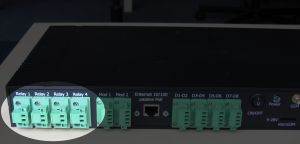
[[Файл:Netmon2 relays.JPG| thumb | 300px | | [[Файл:Netmon2 relays.JPG| thumb | 300px | The relay outputs on the front panel]] | ||
There are four groups of relay outputs, output on the connector terminals, on the front panel of the Wiren Board NETMON-2. | |||
SPST contact configuration (two contacts per relay: NO/COM). | |||
Current up to 10A per channel. The module has protection against sparking of the contacts. | |||
{| class="wikitable" | {| class="wikitable" | ||
! | !Parameter | ||
! | !Value | ||
|- | |- | ||
| | |Number of outputs | ||
|4 | |4 | ||
|- | |- | ||
| | |Output type | ||
| | |mechanical relay | ||
|- | |- | ||
| | |Contact configuration | ||
|SPST, | |SPST, normally open | ||
conditions: | |||
off, | |||
K and NO are closed | |||
|- | |- | ||
| | |Maximum switching voltage, AC | ||
|250V | |250V | ||
|- | |- | ||
| | |Maximum switching voltage, DC | ||
|30V | |30V | ||
|- | |- | ||
| | |Maximum switching current, per channel (*) | ||
|10A | |10A | ||
|- | |- | ||
| | |The channel resistance in the open state | ||
|< 100 mOhm | |< 100 mOhm | ||
|- | |- | ||
| | |Voltage isolation between the controller and the output | ||
|1500Vrms | |1500Vrms | ||
|- | |- | ||
| | |Lifetime: number of switches | ||
for load 10A 230V AC, cos φ = 1 | |||
|100 000 | |100 000 | ||
|} | |} | ||
<nowiki>*</nowiki>) | <nowiki>*</nowiki>) Maximum switching current is specified for 230V AC resistive load. | ||
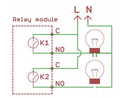
Relays are connected in a phase break.[[File:Relay outputs.png|400px|thumb|none|connection diagram|link=http://contactless.ru/wiki/index.php/%D0%A4%D0%B0%D0%B9%D0%BB:Relay_outputs.png]] | |||
== | == Digital inputs == | ||
=== | ===Purpose=== | ||
Connection of pulse counters, buttons, switches, sensors with "dry contact"output. | |||
=== | ===Technical parameters=== | ||
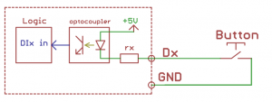
8 | 8 inputs for connection of "dry contacts" with group galvanic isolation. The scheme of inputs is shown in the figure. The terminal is supplied ~ 4.5 V, when the earth current flows a small (1mA), causing the operation of the input. | ||
{| class="wikitable" | {| class="wikitable" | ||
! | !Parameter | ||
! | !Value | ||
|- | |- | ||
| | |Number of inputs | ||
|8 | |8 | ||
|- | |- | ||
| | |Isolated input groups | ||
|1 | |1 | ||
|- | |- | ||
| | |Input type | ||
|" | |"dry contact", | ||
the opening of the current at | |||
earth short | |||
|- | |- | ||
| | |Operation condition | ||
| | |GND input lockout | ||
|- | |- | ||
| | |Tripping current | ||
|1 | |1 mA | ||
|- | |- | ||
| | |Minimum pulse width to trigger | ||
|10 ms | |10 ms | ||
|- | |- | ||
| | |Minimum time between consecutive signals | ||
|5 ms | |5 ms | ||
|- | |- | ||
| | |Voltage of "wetting" | ||
|4. | |4.5 V | ||
|} | |} | ||
=== | ===Connection=== | ||
==== | ==== Sensors/counters with pulse outputs/buttons. ==== | ||
Such devices form a signal by closing two wires that are suitable for them. Connect one wire to the GND terminal of the module. Connect the second wire to the Dx terminal. Some counters have a pulse output on the optocoupler, then the two wires have a polarity - "plus" and "minus". In this case, minus is connected to GND, plus to Dx. | |||
==== | ==== Devices with open collector output. ==== | ||
The device and the module must have a common ground. Connect the open collector output to the Dx terminal. | |||
The module inputs are galvanically isolated from the controller. Therefore, the ground GND of the module and the controller may be different. | |||
[[ | [[File:DI.png|300px|thumb|none|Digital inputs DI|link=http://contactless.ru/wiki/index.php/%D0%A4%D0%B0%D0%B9%D0%BB:DI.png]] | ||
== | == Front panel connectors == | ||
[[Файл:Netmon2 front panel photo.jpg|thumb|700px| передняя панель]] | [[Файл:Netmon2 front panel photo.jpg|thumb|700px| передняя панель]] | ||
{| class="wikitable" | {| class="wikitable" | ||
! colspan="4" rowspan="1" | | ! colspan="4" rowspan="1" |Relay outputs | ||
! colspan="1" rowspan="2" |* | ! colspan="1" rowspan="2" |* | ||
! colspan="1" rowspan="2" | | ! colspan="1" rowspan="2" |Analog inputs | ||
! colspan="1" rowspan="2" | | ! colspan="1" rowspan="2" |Second extension module | ||
! colspan="4" rowspan="2" | | ! colspan="4" rowspan="2" |Discrete inputs, dry contact type" | ||
! colspan="2" rowspan="2" | | ! colspan="2" rowspan="2" |Analog inputs | ||
! colspan="1" rowspan="2" | | ! colspan="1" rowspan="2" |Analog RX inputs | ||
! colspan="1" rowspan="2" |1- | ! colspan="1" rowspan="2" |1-Wire | ||
! colspan="1" rowspan="2" |RS-485 #1 | ! colspan="1" rowspan="2" |RS-485 #1 | ||
! colspan="1" rowspan="2" |RS-485 #2 CAN | ! colspan="1" rowspan="2" |RS-485 #2 CAN | ||
| Строка 358: | Строка 360: | ||
|} | |} | ||
== | == Temperature and humidity sensor == | ||
Wiren Board NETMON-2 | Wiren Board NETMON-2 can be equipped with built-in temperature and humidity sensor. For more information, see [[Датчик AM2320/en| AM2320 sensor]]. | ||
== | ==Software== | ||
[[Программное обеспечение Wiren Board/en|Wiren Board software]] | |||
== | == Peripheral connection == | ||
See [[Wiren Board 5: Подключение периферийных устройств/en| Wiren Board 5: Connecting peripherals]] | |||
See [[Поддерживаемые устройства/en| Supported devices]] | |||
Текущая версия на 19:32, 25 июля 2019
Wiren Board NETMON-2 is a universal controller for automation with open software based on Linux, a built-in GSM modem and designed in a case for installation in a 19" rack.
Designed for monitoring of network and telecommunication equipment, polling of sensors and counters, remote power management.
Technical specifications
The controller is identical in hardware to the set of:
2. WBIO-DO-R10A-4- 4 SPST 10A/230V relays
3. WBIO-DI-DR-8
4. Backup power module - optional.
5. 2х extension modules - опция
All inputs and outputs of the controller and extension modules are connected to detachable terminals on the front panel.
| General | |
|---|---|
| Processor | Freescale i.MX28 454 MHz ARM9 |
| Memory RAM|DDR2 SDRAM 128 MB | |
| Nonvolatile memory | 4 GB eMMC |
| Operating system | Debian Linux 7.0. Mainline kernel 4.1. |
| Overall dimensions | 1U 19", depth 20 cm
431x203x43 mm |
| Operation | operating temperature - -25...+70C (-40..+70 ° C on request). |
| Wireless interfaces | |
|---|---|
| Wi-Fi | 802.11 b/g/n 2.4 GHz (optional) |
| GSM/GPRS | 850/900/1800/1900 MHz. GPRS class 12. 85.6 kbps (downlink).
SIM-card format microSIM |
| Bluetooth | 4.0, Bluetooth Low Energy |
| Packet radio 433 MHz | module RFM69H. To communicate with devices on Noolite, sensors Oregon(option) |
| Z-Wave | (optional) |
| Wired interfaces | |
|---|---|
| Ethernet | 10/100 Mbit/s, 8P8C Plug, passive PoE |
| USB 2.0 | 1 port. Working in USB Host or USB Device mode |
| 2xRS-485 | Without galvanic isolation.
there is software support for Modbus RTU, Uniel, HDL, mercury, Milur, ivtm PROTOCOLS |
| CAN | multiplexed with one RS-485. |
| Debug console | Debug UART Connects via USB-UART adapter inside the case. |
| 1-Wire | Temperature sensor connection |
| "'Connect sensors'" | |
|---|---|
| 4x ADC | range 0-28V |
| 1xInputs for resistive sensors | Connect to 10 kω thermistor, use the ADC as 2.5 V. |
| 4x DI (digital input) | |
| "'Outputs'" | |
| 4x"Open collector" | 28V/2A, contactor control, LED strips, etc. |
| "'Other interfaces'" | |
|---|---|
| 1xsound emitter | Buzzer. |
| Real time clock | backup battery |
| Watchdog | Separate hardware watchdog, restarting the device entirely by power |
| 2х expansion module slot | |
| "food" | |
|---|---|
| Supply voltage | 7-28V |
| Power consumption | <3 W (peak - up to 12 W) |
| Operation from backup battery | backup power Module (Option) |
| twisted pair power | Passive Power over Ethernet]] |
= Package =
- Wiren Board NETMON-2 controller
- terminals
- 19" rack mount housing kit
Preparation for work
- Remove the top cover of the housing
- Connect the backup power module to the controller
- Install rack mounts
- Install the top cover of the housing, tighten the screws included in the kit
Power Supply
External power supply
The permissible power range is 5-22V. The average consumption of the device is 1.5-2 watts. But since the GSM module consumes up to 8W impulsively, it is recommended to use power supplies with a power of at least 10W.
The power connector for the standard jack 5.5x2.1mm is located on the front panel.
Power over Ethernet
Power-over-Ethernet (Passive PoE) is supported via RJ45 connector on the front panel. Supports the standard voltage of 12V and 15V. See Power over Ethernet/en.
Battery
The Wiren Board NETMON-2 can be equipped with one or two Li-Ion (Li-Pol) batteries with a maximum voltage of 4.2 V. When the power is connected, the battery is charged with a current of up to 0.5 A.
There is protection against charging at low temperatures and overheating.
GSM/GPRS-modem
The GSM antenna is connected to the SMA connector on the front panel of the controller. If the GSM signal is weak, it is recommended to use a remote antenna and place it away from the controller.
USB port
Wiren Board NETMON-2 has one USB port (Host, type A) inside the case. The port is designed to connect Wi-Fi sticks, 3G modems, etc.
External load switching
There are four groups of relay outputs, output on the connector terminals, on the front panel of the Wiren Board NETMON-2.
SPST contact configuration (two contacts per relay: NO/COM).
Current up to 10A per channel. The module has protection against sparking of the contacts.
| Parameter | Value |
|---|---|
| Number of outputs | 4 |
| Output type | mechanical relay |
| Contact configuration | SPST, normally open
conditions: off, K and NO are closed |
| Maximum switching voltage, AC | 250V |
| Maximum switching voltage, DC | 30V |
| Maximum switching current, per channel (*) | 10A |
| The channel resistance in the open state | < 100 mOhm |
| Voltage isolation between the controller and the output | 1500Vrms |
| Lifetime: number of switches
for load 10A 230V AC, cos φ = 1 |
100 000 |
*) Maximum switching current is specified for 230V AC resistive load.
Relays are connected in a phase break.
Digital inputs
Purpose
Connection of pulse counters, buttons, switches, sensors with "dry contact"output.
Technical parameters
8 inputs for connection of "dry contacts" with group galvanic isolation. The scheme of inputs is shown in the figure. The terminal is supplied ~ 4.5 V, when the earth current flows a small (1mA), causing the operation of the input.
| Parameter | Value |
|---|---|
| Number of inputs | 8 |
| Isolated input groups | 1 |
| Input type | "dry contact",
the opening of the current at earth short |
| Operation condition | GND input lockout |
| Tripping current | 1 mA |
| Minimum pulse width to trigger | 10 ms |
| Minimum time between consecutive signals | 5 ms |
| Voltage of "wetting" | 4.5 V |
Connection
Sensors/counters with pulse outputs/buttons.
Such devices form a signal by closing two wires that are suitable for them. Connect one wire to the GND terminal of the module. Connect the second wire to the Dx terminal. Some counters have a pulse output on the optocoupler, then the two wires have a polarity - "plus" and "minus". In this case, minus is connected to GND, plus to Dx.
Devices with open collector output.
The device and the module must have a common ground. Connect the open collector output to the Dx terminal.
The module inputs are galvanically isolated from the controller. Therefore, the ground GND of the module and the controller may be different.
Front panel connectors
| Relay outputs | * | Analog inputs | Second extension module | Discrete inputs, dry contact type" | Analog inputs | Analog RX inputs | 1-Wire | RS-485 #1 | RS-485 #2 CAN | |||||||
|---|---|---|---|---|---|---|---|---|---|---|---|---|---|---|---|---|
| Relay 1 | Relay 2 | Relay 3 | Relay 4 | |||||||||||||
| mod-1 | mod-2 | D1-D2 | D3-D4 | D5-D6 | D7-D8 | A1-A2 | A3-A4 | R1-R2 | ||||||||
| NO | NO | NO | NO | 4 | AGND | O3 | GND | GND | GND | GND | GND | GND | GND | GND | B | B/H |
| 3 | MOD1_A2 | O2 | DI2 | DI4 | DI6 | DI8 | A2 | A4 | R2 | 5V | A | A/L | ||||
| COM | COM | COM | COM | 2 | MOD1_A1 | O1 | DI1 | DI3 | DI5 | DI7 | A1 | A3 | R1 | W1 | GND | GND |
| 1 | AGND | -- | GND | GND | GND | GND | 5V | 5V | GND | GND | V+ | V+ | ||||
Temperature and humidity sensor
Wiren Board NETMON-2 can be equipped with built-in temperature and humidity sensor. For more information, see AM2320 sensor.
==Software==


