Wiren Board 5/en: различия между версиями
(Новая страница: «If the GSM signal is weak, it is recommended to use a remote antenna and place it away from the controller.») |
(Новая страница: « == Device pictures and drawings == {{WBPicturesNoDrawing|1}}») |
||
| (не показано 56 промежуточных версий 2 участников) | |||
| Строка 42: | Строка 42: | ||
[[Модули_расширения/en | '''Extension modules''']] are small boards installed inside the case of the Wiren Board 5 and extend its functionality: additional ports RS-485, RS-232, relay outputs, etc. | [[Модули_расширения/en | '''Extension modules''']] are small boards installed inside the case of the Wiren Board 5 and extend its functionality: additional ports RS-485, RS-232, relay outputs, etc. | ||
The controller has two slots for connecting | The controller has two slots for connecting extension modules. Each module has 3 external terminals. | ||
| Строка 82: | Строка 82: | ||
If the GSM signal is weak, it is recommended to use a remote antenna and place it away from the controller. | If the GSM signal is weak, it is recommended to use a remote antenna and place it away from the controller. | ||
== | == Wired interfaces == | ||
''' | '''Ethernet interface''' supports 10/100 Mbps. In revisions with 5.8 there is a second Ethernet port. | ||
Так же присутствует один порт USB 2.0. Работает в режиме USB Host или USB Device. Управление питанием отдельных USB-устройств описано в статье [[Питание USB-портов| | Так же присутствует один порт USB 2.0. Работает в режиме USB Host или USB Device. Управление питанием отдельных USB-устройств описано в статье [[Питание USB-портов/en|USB port power supply]]. | ||
[[File:rs-485-setup-configs.png|thumb|right|300 px| | [[File:rs-485-setup-configs.png|thumb|right|300 px|Configuration is set through the section ''Configs'' [[RS-485:Настройка через веб-интерфейс/en|of the web interface]]]] | ||
[[ | [[RS-485/en|'''RS-485''']] — two-wire bus communication standard. | ||
The controller has 2 RS-485 ports + 2 more ports can be added [[Wiren Board 5: Модуль расширения RS485-ISO/en| by RS-485 extension modules]]. | |||
The article [[RS-485:Физическое подключение/en|RS-485:Physical connection]] will help you to choose and lay cables correctly. | |||
[[RS-485:Настройка через веб-интерфейс/en| Setting up the connection]] of devices is carried out in the web interface. | |||
Basically in Wiren Board,[[Драйвер_wb-mqtt-serial/en| driver WB-mqtt-serial ]] works through the system of [[MQTT/en| MQTT]]-messages with connected RS-485 devices. | |||
'''[[CAN/en| CAN]]''' is the standard for two-wire bus communication. | |||
The controller is multiplexed (output to the same terminals) with a second RS-485 port. | |||
'''[[1-Wire/en | 1-Wire]]''' — is a bus for connecting external sensors on two or three wires. Since this is a bus, you can connect multiple devices to the same 1-Wire port. | |||
The controller software supports the connection of DS18B20 type temperature sensors. | |||
It is convenient to use +5V output to power the sensors. | |||
It is protected from short circuit and high voltage. When the controller is powered by a battery, the +5V output remains active. | |||
There is also a software control of this output (it can be disabled). | |||
== Universal inputs/outputs A1-A4 == | |||
Universal channel Ah combines three functions and can work as: | |||
* [[ | * Output [[Управление низковольтной нагрузкой/en|open collector]] - key (3A/30V), closing the ground output. | ||
* [[ADC | Analog input]] with 0-28V measurement range. | |||
* | |||
* [[DI | Digital input ]] — is triggered when the voltage at the terminal is 5 V | |||
== | == Resistive inputs R1 and R2 == | ||
Can operate in modes: | |||
* resistance measurements 1-30kω | |||
* voltage measurements in the range of 0-3.0 V | |||
* digital input | |||
"R2 input only is only in version 5.3." | |||
== Terminal blocks == | |||
[[Файл:WB5 подписи1.jpg| thumb | 500px|Wiren Board 5]] | [[Файл:WB5 подписи1.jpg| thumb | 500px|Wiren Board 5]] | ||
[[File:Wago.jpeg|thumb|400px| | [[File:Wago.jpeg|thumb|400px|Working with WAGO 250 terminals]] | ||
{| | {| border="1" width="700" class="wikitable" style="text-align:center" | ||
| | | | ||
''' | '''signature''' | ||
|| | || "'Max. V, I"' | ||
| width="10%" | ''' | | width="10%" | "'state"' "'default"' | ||
| width="60%"|' | | width="60%"|"'Function"' | ||
|- | |- | ||
! colspan="4"| | ! colspan="4"| Top row, left block | ||
|- | |- | ||
| | | "'Vin"' || 28V | | |Power supply, reverse polarity protection | ||
|- | |- | ||
| | | "'GND"'|| || ||"ground" minus power supply | ||
|- | |- | ||
! colspan="6"| | ! colspan="6"| Top row, right block | ||
|- | |- | ||
| | | "'O1-O3"' || | || | || |Inputs/outputs of the 1st extension module | ||
|- | |- | ||
| | | "'O1-O3"' || | ||| || |Inputs/outputs of the 2nd extension module | ||
|- | |- | ||
! colspan="8"| | ! colspan="8"| Bottom row, right block | ||
|- | |- | ||
| '''A1-A4''' || 28V , 2A || | | '''A1-A4''' | | 28V , 2A || High Z || [[Управление низковольтной нагрузкой/en|open collector outputs]], [[ADC/en|ADC]], digital inputs, key protection against inductive load. | ||
|- | |- | ||
| '''R1-R2*''' || 5V || High Z || | | '''R1-R2*''' || 5V || High Z || Resistive sensors, [[ADC/en|ADC]], digital inputs | ||
|- | |- | ||
| '''GND''' ||| || || | | '''GND'''||| || || For easy connection of external sensors | ||
|- | |- | ||
| '''W1''' || 30V || 3. | | '''W1''' || 30V || 3.3 V || [[1-Wire/en|1-Wire]], GPIO | ||
|- | |- | ||
| '''5V out''' || 5V, 0. | | '''5V out''' || 5V, 0.5 A || 5V || 5V Output. Short circuit protection. Software on/off. | ||
|- | |- | ||
| '''A''' || | | '''A''' || 30 V || 0V || rowspan="2"|port [[Special:MyLanguage/RS-485|RS-485]] (/dev/ttyAPP1) | ||
|- | |- | ||
| '''B''' || | | '''B''' || 30 V || +5V | ||
|- | |- | ||
|- | |- | ||
| '''L''' || 30 V || 0V || | | '''L''' || 30 V || 0V || rowspan="2"|can Port or [[Special:MyLanguage/RS-485|RS-485]] (/dev/ttyAPP4). | ||
RS-485 connection: A to terminal "'L"', B to terminal "'H"'. | |||
|- | |- | ||
| '''H''' || | | '''H''' || 30 V || +5V | ||
|- | |- | ||
| '''Vout*''' || 1A || | | '''Vout*''' || 1A | | | | Power output. The input voltage is connected through the diode. | ||
|- | |- | ||
|} | |} | ||
"*" depends on the [[Wiren_Board:_Аппаратные_ревизии/en|hardware revision]] | |||
All inputs are protected against supply voltage (up to 28 V) and impulse noise. | |||
Type "250" terminals are used as interface terminals in the controller. | |||
These are self-locking clips. When the cleaned single-wire is inserted into the socket, it is automatically clamped with a spring latch. | |||
To insert stranded wires, it is necessary to press the spring by pressing the clip button. | |||
The button has a slot for a screwdriver. | |||
To remove the wire, you need to press the spring by pressing the clip button and pull out the wire. | |||
== Other interfaces == | |||
[[WB_Debug_Console/en |Debug port]] - you can directly access the controller console by connecting to it. Through it you can also interact with the bootloader and monitor the operating system boot (serial console). | |||
[[Buzzer/en | "Buzzer"]] — beeps, its frequency is adjustable. | |||
The real-time clock RTC is powered by an internal backup battery. | |||
[[ | Revisions 5.3 and 5.6 also contain: | ||
*[[Consumer IR/en|IrDA]] | |||
* Digital audio output - S/PDIF, TOSLINK connector. | |||
== Watchdog == | |||
A separate hardware watchdog that reboots the entire controller on power when the | |||
software freezes. | |||
[[Hardware_Watchdog_Disable/en | Hardware watchdog disable]] | |||
== Power Supply == | |||
The controller has three external inputs for power connection: | |||
* DC jack - standard plug connector (5.5x2.1mm) on the left side of the case. | |||
* Terminals Vin and GND in the controller of audit 5.8 and above: two terminal Vin, to which you can connect two independent power supply for redundancy. The grounds of the power supplies must be connected and connected to the GND terminal. | |||
* | * Power-over-Ethernet (PoE Passive). Read more [[Power over Ethernet/en|Power over Ethernet]]. | ||
It is possible to simultaneously connect the sources to different inputs, including different voltages. | |||
For backup power, you can connect the internal module [[WBMZ-BATTERY_-_модуль_резервного_питания/en | WBMZ-BATTERY ]] with Li-Ion (Li-Pol) battery. | |||
Valid power range is '''7-28V'''. | |||
The average consumption of the Board is 1.5-2 watts. But since the GSM module pulse consumes up to 8 watts, it is recommended to use power supply units with power not less than '''10 W'''. | |||
== Supported devices == | |||
[[Периферийные устройства с интерфейсом RS-485 серии WB-xxxx/en |Devices of our production with the RS-485 interface]] | |||
[[Special:MyLanguage/Поддерживаемые устройства|Supported Devices]] | |||
[[ | [[Wiren Board 5: Подключение периферийных устройств/en|Connection of peripheral devices]] | ||
== Detailed technical description of the controller board == | |||
[[ | [[Файл:WB5.3razm.png|thumb|400px|Board side]] | ||
The article [[Wiren_Board_5:Схемотехника/en| Wiren Board 5: Hardware]] describes some of the features of work and the device inputs, the power supply circuit of the controller. | |||
[[ | [[WB 5: Errata/en| Hardware errors/features of Wiren Board 5 ]] found in the operation of the controller. | ||
[[Wiren Board: Аппаратные ревизии/en| Hardware revisions]] — the description of changes in the controller board. | |||
Table of matching processor and GPIO signals on the board for revisions: | |||
[[Wiren Board: | [[Wiren Board 5.5:Список GPIO/en|rev. 5.5 (5.6, 5.6.1)]], [[Wiren Board 5.8:Список GPIO/en|rev. 5.8 (5.9)]], [[Wiren Board 5:Список GPIO/en|rev. 5.3]] | ||
[[Работа с GPIO/en|Working with GPIO]] — how to work directly with GPIO. | |||
[[ | [[WB5_root_password_recovery/en|Wiren Board 5: WB root password recovery]] | ||
== | == Device pictures and drawings == | ||
{{Wbincludes:WBPicturesNoDrawing|1}} | {{Wbincludes:WBPicturesNoDrawing|1}} | ||
{{Wbincludes:WBPicturesNoDrawing|2}} | {{Wbincludes:WBPicturesNoDrawing|2}} | ||
Текущая версия на 17:02, 3 июля 2019
General characteristics
| Processor | Freescale i.MX28 454 MHz ARM9 |
| Memory RAM| DDR2 SDRAM 128 MB | |
| Nonvolatile memory | 4 GB eMMC |
| Operating system | Debian Linux 7.0. Mainline kernel 4.1. |
| Dimensions | Enclosure on a DIN rail with a width of 6M.
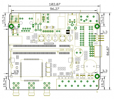
106.25x90.2x57.5 mm. Size without case: 103x87x20 mm. |
| Operation | operating temperature - -25...+70C
(-40..+70 ° C on request). |
| Power | 7-28VDC |
Product page and online store: Wiren Board 5
It is recommended to read the Getting started article to start working with the controller.
Программное обеспечение Wiren Board/en
The modularity of the controller
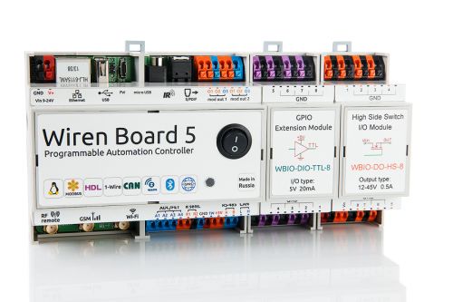
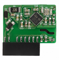
Extension modules are small boards installed inside the case of the Wiren Board 5 and extend its functionality: additional ports RS-485, RS-232, relay outputs, etc.
The controller has two slots for connecting extension modules. Each module has 3 external terminals.
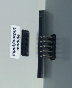
Input/output modules dock with the side connector on the WB5 on the right side of the case, adding 8 to 16 digital or analog ports.
Up to 8 modules can be connected in series: up to 4 input modules (type I) and up to 4 output modules (type O and I/O).
Модуль резервного питания - additional mezzanine board is installed on the second level in the controller case.
Contains Li-Ion (Li-Pol) battery capacity of 1800 mAh, provides the controller up to 3 hours of opertation.
Wireless interfaces
Cellular module - modem 2G (GPRS), 3G (UMTS) or NB-IoT is installed in the controller during production. Requires a MicroSIM card.
The modem allows you to send and receive SMS, connect to the Internet.
Wi-Fi of the Wiren Board can be configured to work in one of three modes:
in Hotpoint mode, enabled by default (the name is WirenBoard without password, the address of the controller in the generated network is: 192.168.42.1)
- client mode
- simultaneous operation in both Hotpoint and client modes
Bluetooth 4.0 (Bluetooth Low Energy) — you can track the proximity of other Bluetooth devices, such as a mobile phone or Bluetooth tag.
USB stick Z-Wave gives support for standard Z-Wave devices.
433MHz Packet radio - the RFM69H radio module is installed in the controller during production.
Allows you to connect Noolite devices, Oregon sensors to the controller.
Wi-Fi, GSM and 433 MHz radio antennas are connected to SMA connectors.
If the GSM signal is weak, it is recommended to use a remote antenna and place it away from the controller.
Wired interfaces
Ethernet interface supports 10/100 Mbps. In revisions with 5.8 there is a second Ethernet port.
Так же присутствует один порт USB 2.0. Работает в режиме USB Host или USB Device. Управление питанием отдельных USB-устройств описано в статье USB port power supply.
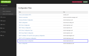
RS-485 — two-wire bus communication standard.
The controller has 2 RS-485 ports + 2 more ports can be added by RS-485 extension modules.
The article RS-485:Physical connection will help you to choose and lay cables correctly.
Setting up the connection of devices is carried out in the web interface.
Basically in Wiren Board, driver WB-mqtt-serial works through the system of MQTT-messages with connected RS-485 devices.
CAN is the standard for two-wire bus communication. The controller is multiplexed (output to the same terminals) with a second RS-485 port.
1-Wire — is a bus for connecting external sensors on two or three wires. Since this is a bus, you can connect multiple devices to the same 1-Wire port. The controller software supports the connection of DS18B20 type temperature sensors.
It is convenient to use +5V output to power the sensors. It is protected from short circuit and high voltage. When the controller is powered by a battery, the +5V output remains active. There is also a software control of this output (it can be disabled).
Universal inputs/outputs A1-A4
Universal channel Ah combines three functions and can work as:
- Output open collector - key (3A/30V), closing the ground output.
- Analog input with 0-28V measurement range.
- Digital input — is triggered when the voltage at the terminal is 5 V
Resistive inputs R1 and R2
Can operate in modes:
- resistance measurements 1-30kω
- voltage measurements in the range of 0-3.0 V
- digital input
"R2 input only is only in version 5.3."
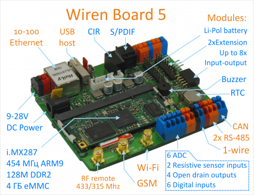
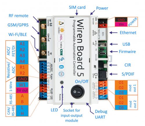
Terminal blocks
|
signature |
"'Max. V, I"' | "'state"' "'default"' | "'Function"' | ||||
| Top row, left block | |||||||
|---|---|---|---|---|---|---|---|
| "'Vin"' | | |Power supply, reverse polarity protection | ||||||
| "'GND"' | "ground" minus power supply | ||||||
| Top row, right block | |||||||
| "'O1-O3"' | Inputs/outputs of the 1st extension module | ||||||
| "'O1-O3"' | Inputs/outputs of the 2nd extension module | ||||||
| Bottom row, right block | |||||||
| | 28V , 2A | High Z | open collector outputs, ADC, digital inputs, key protection against inductive load. | |||||
| R1-R2* | 5V | High Z | Resistive sensors, ADC, digital inputs | ||||
| GND | For easy connection of external sensors | ||||||
| W1 | 30V | 3.3 V | 1-Wire, GPIO | ||||
| 5V out | 5V, 0.5 A | 5V | 5V Output. Short circuit protection. Software on/off. | ||||
| A | 30 V | 0V | port RS-485 (/dev/ttyAPP1) | ||||
| B | 30 V | +5V | |||||
| L | 30 V | 0V | can Port or RS-485 (/dev/ttyAPP4).
RS-485 connection: A to terminal "'L"', B to terminal "'H"'. | ||||
| H | 30 V | +5V | |||||
| Vout* | | | | Power output. The input voltage is connected through the diode. | ||||||
"*" depends on the hardware revision
All inputs are protected against supply voltage (up to 28 V) and impulse noise.
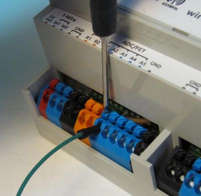
Type "250" terminals are used as interface terminals in the controller. These are self-locking clips. When the cleaned single-wire is inserted into the socket, it is automatically clamped with a spring latch. To insert stranded wires, it is necessary to press the spring by pressing the clip button. The button has a slot for a screwdriver. To remove the wire, you need to press the spring by pressing the clip button and pull out the wire.
Other interfaces
Debug port - you can directly access the controller console by connecting to it. Through it you can also interact with the bootloader and monitor the operating system boot (serial console).
"Buzzer" — beeps, its frequency is adjustable.
The real-time clock RTC is powered by an internal backup battery.
Revisions 5.3 and 5.6 also contain:
- IrDA
- Digital audio output - S/PDIF, TOSLINK connector.
Watchdog
A separate hardware watchdog that reboots the entire controller on power when the software freezes.
Power Supply
The controller has three external inputs for power connection:
- DC jack - standard plug connector (5.5x2.1mm) on the left side of the case.
- Terminals Vin and GND in the controller of audit 5.8 and above: two terminal Vin, to which you can connect two independent power supply for redundancy. The grounds of the power supplies must be connected and connected to the GND terminal.
- Power-over-Ethernet (PoE Passive). Read more Power over Ethernet.
It is possible to simultaneously connect the sources to different inputs, including different voltages.
For backup power, you can connect the internal module WBMZ-BATTERY with Li-Ion (Li-Pol) battery.
Valid power range is 7-28V. The average consumption of the Board is 1.5-2 watts. But since the GSM module pulse consumes up to 8 watts, it is recommended to use power supply units with power not less than 10 W.
Supported devices
Devices of our production with the RS-485 interface
Connection of peripheral devices
Detailed technical description of the controller board
The article Wiren Board 5: Hardware describes some of the features of work and the device inputs, the power supply circuit of the controller.
Hardware errors/features of Wiren Board 5 found in the operation of the controller.
Hardware revisions — the description of changes in the controller board.
Table of matching processor and GPIO signals on the board for revisions:
rev. 5.5 (5.6, 5.6.1), rev. 5.8 (5.9), rev. 5.3
Working with GPIO — how to work directly with GPIO.
Wiren Board 5: WB root password recovery
Device pictures and drawings
По ссылкам ниже вы можете скачать изображения и чертежи устройства Wiren_Board-5.8.
Corel Draw 2018: Wiren_Board-5.8.cdr.zip
Corel Draw PDF: Wiren_Board-5.8.cdr.pdf
Autocad 2013 DXF: Мы еще не подготовили чертеж этого устройства. Вы можете запросить чертеж устройства "Контроллер Wiren Board 5.8" на портале техподдержки Wiren Board (необходима регистрация).
По ссылкам ниже вы можете скачать изображения и чертежи устройства Wiren_Board-5.9.
Corel Draw 2018: Wiren_Board-5.9_new.cdr.zip
Corel Draw PDF: Wiren_Board-5.9_new.cdr.pdf
Autocad 2013 DXF: Мы еще не подготовили чертеж этого устройства. Вы можете запросить чертеж устройства "Контроллер Wiren Board 5.9" на портале техподдержки Wiren Board (необходима регистрация).
