- 1,778 pieces are already at the warehouse
- 2000 more in 2-3 months
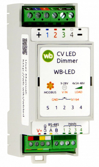
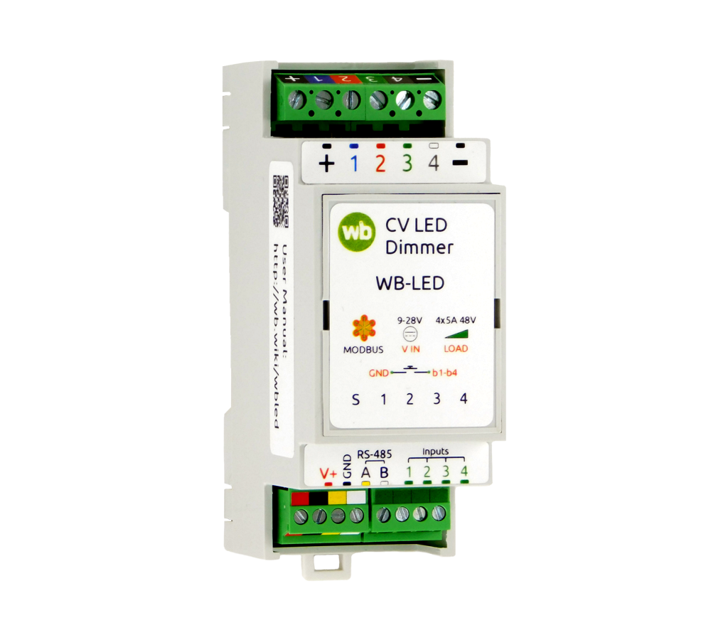
Four-channel LED strip dimmer with RS-485 interface and 4 discrete inputs for connecting switches. Supports all types of LED strips with voltage up to 48 V.
Used to control artistic LED lighting in smart home systems for residential and commercial premises. Allows you to organize local backlight control without using a controller. To increase power, an amplifier WB-AMPLED is used.
MAIN FEATURES
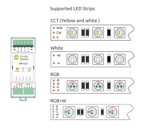
- Select LED strip type: RGB, RGB+W, CCT or W.
- Smooth brightness control throughout the entire range.
- Adjustable PWM frequency from 100 Hz to 24 kHz to select the optimal control mode without flicker or noise.
- Flexible control settings from switches and recognition of 4 types of clicks for organizing local control of lighting scenes without a controller.
- Indication of channel status for quick diagnostics.
- Compact housing for DIN rail.
- Fast and simple integration into automation and monitoring systems.
Supports Fast Modbus ⚡, which allows you to instantly deliver input states and click counter values to the Wiren Board controller.
Technical specifications:
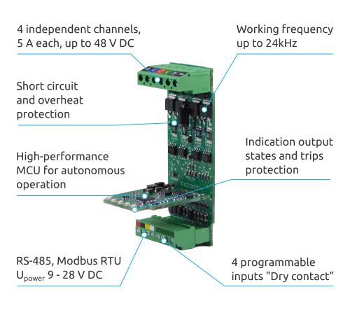
- 4 channels of 5 A, up to 48 V DC. The channels can be combined and used as a single channel 20 A dimmer.
- PWM frequency from 100 Hz to 24 kHz, changeable in settings.
- Short circuit and overheat protection.
- Indication output states and trips protection.
-
Four universal programmable digital inputs:
- supported click types: short, double, long, short and then long;
- various actions can be assigned to each type of click on any input.
- Supply voltage: 9 to 28 VDC.
- Interface: RS-485, Modbus RTU.
- Housing for DIN rail, 2M (36 x 90 x 58 mm).
The dimmer can work stand-alone or paired with a controller.
Depending on the selected mode, the dimmer can work with strips:
- colored (RGB, RGB+W),
- yellow and white (CCT),
- and plain white.
In some modes, several strips of the same or different types can be connected to the dimmer and each of them can be controlled separately.
See the documentation for connection diagrams and available modes.
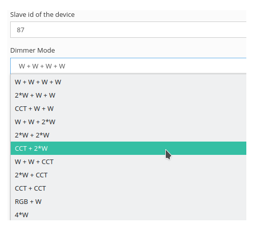
Wiren Board controller's web intervace allows to:
- select the operating mode and assign actions to inputs;
- configure input parameters: debounce time, double and long press time, rate of change of brightness and saturation when pressing the button;
- set the lower and upper dimming thresholds for each channel, change the PWM frequency;
- enable or disable polling of channels and inputs.
When used with other equipment, the dimmer can be configured via RS-485 bus using Modbus protocol. The register table is open, well documented and available on our website.
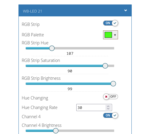
Working stand-alone the dimmer can be controlled by buttons connected to inputs. Working with a controller, both by buttons and via the RS-485 bus.
Regardless of connection method, it is possible to:
- change the brightness and saturation for all types of strips;
- change color of color strips;
- change color temperature of yellow-white strips;
- turn strips on and off.
When working with the Wiren Board controller, the dimmer can be controlled from the web interface and automation scripts, and when used with other equipment, by writing values to Modbus registers.
The dimmer sends status of inputs and outputs as well as other information that can be used in automation via RS-485 bus.
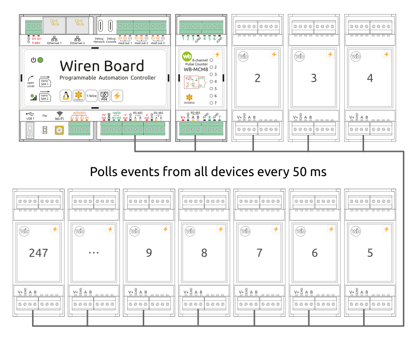
All Wiren Board devices, in addition to the standard Modbus RTU, can work with its extension Fast Modbus ⚡, which adds new features:
- instant polling of input states and measured values via events;
- quick search for devices connected to the controller;
- resolving address collisions on the bus.
Additional features are enabled automatically - if the device supports extension, the controller driver will work with the device quickly Modbus if the device does not know anything about the extension - it will work using standard Modbus RTU.
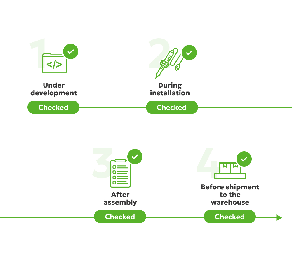
We develop and manufacture all Wiren Board devices ourselves. All devices undergo multi-stage quality control:
- During development — checking the components used for compliance with the declared characteristics and testing the prototype device at extreme operating conditions.
- After installing SMD components — automated optical inspection.
- After soldering the lead components — visual inspection of soldering.
- After assembling the device — functional testing on an automated stand.
- When shipped to the warehouse — control of completeness, stickers, appearance.
Thanks to this approach, the failure rate is no more than 0.5% of all released devices. Read more in the article About device reliability.
If the device fails within two years from the date of purchase, we will replace it for free without the need to send it to a service center.
